seat Workshop Repair Guides

SEAT Workshop Service and Repair Manuals

Exhaust system (Altea, Altea XL, Leon) > < Lambda probeG39 withheating for the lambda probeZ19 Removing and installing
Removing and installing exhaust gas recirculation cooler (Ibiza)
t  Removing → Anchor
t  Installing → Anchor
Check the tool and equipment equivalence table according to the applicability between Seat / VW / Audi / Skoda → Chapter
   
Special tools and workshop equipment required
t  Hose clamp -3094-, see equivalent → Anchor
t  Collecting tray -VAS 6208-, see equivalent → Anchor
t  Pliers for spring-loaded band-type clamps -VAS 6499-, see equivalent → Anchor

   
t  Wrench kit 17 mm -T10395-, see equivalent → Anchor
  W00-10767
t  Torque wrench -VAG 1331-, see equivalent → Anchor.
t  Wrench kit -3337-, see equivalent → Anchor
  W00-0427
Removing
  E10-10087
–  Loosen the engine cover at the locations -arrows- and remove.
–  Version for cold climate zones: Unplug electrical connector -2-.
–  Press release tabs and detach crankcase breather hose -1-.
–  Disconnect vacuum hose -arrow-.
–  Unscrew the screw -3-, swing air pipe with intake hose to the rear and pull off from the turbocharger.
  A21-10541
–  Unscrew the union nut of the oil supply line using the socket wrench insert -T40055-, the square ratchet of the torque wrench -VAG 1331--1- and a 13 mm spanner.
  E17-10020
–  Remove bolts -arrows-.
–  Loosen hose clip -1- and remove pulsation damper -2-.
Loosen particulate filter.
t  -1- Separate exhaust gas temperature sender 1 -G235- connector
t  Detach the connector -2- of the exhaust gas temperature sender 3 -G495-.
t  Detach the connector -3- of the exhaust gas pressure sensor 4 -G648-.
  A21-10478
t  Detach the connector -4- of the Lambda probe -G39-.
  N26-10416
–  Unplug connector from pressure differential sender -G505--3-.
–  Unscrew bolt -2-, remove pressure differential sender -G505-, free hoses -1-.
–  Pull lines out of retainers on engine and remove heat shield from particulate filter; if necessary remove cable ties.
  A26-11013
–  Unscrew the bolt -1- from the centre support of the particle filter mount.
–  Remove securing clamp -2- between particulate filter and turbocharger.
  A26-11017
–  Remove the screws -1- and take off the heat shield for drive shaft on the right side.
–  Detach right drive shaft from gearbox flange.
  Note
The flexible joint in the front exhaust pipe must not be bent more than 10° - otherwise it can be damaged.
  N17-10184
–  Fix the transport lock -T10403--arrow- on the decoupling element in the front exhaust pipe.
  N26-10517
–  Unscrew bolts -1- and then nuts -2-.
  N26-10535
–  Pull the particulate filter from its brackets in the mountings -arrows-.
  A26-10956
–  Slacken the fastening nuts -arrows- of the clamping sleeve and then lower the exhaust pipe to the rear.
  V26-0733
–  Remove the particulate filter -1- and fix accordingly on the steering box -2- in order not to damage it.
  E10-10110
–  Remove connection pipe -2- leading to cooler for exhaust gas recirculation.
–  Unscrew connecting pipe -1- only at exhaust gas recirculation cooler -arrows-.
  S26-0317
–  Unscrew the bolts -1, 5- and the hollow bolts -9, 10-; remove the exhaust gas turbocharger bracket together with the oil return hose.
  E26-10056
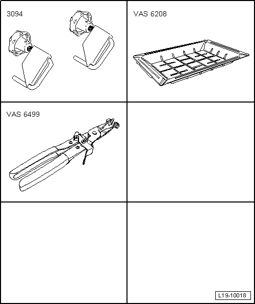
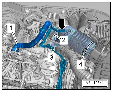
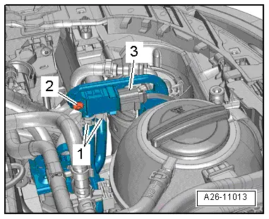
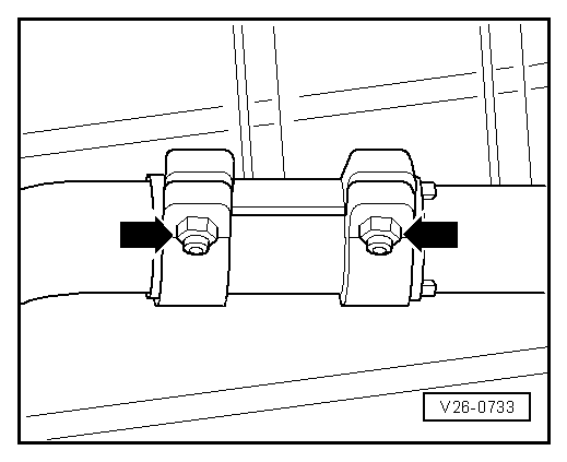
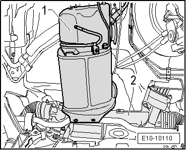
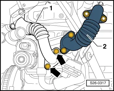
–  Clamp off the coolant hoses -2, 3- with hose clamps -3094- and detach hoses from the exhaust gas recirculation radiator. For this purpose loosen the hose clamp.
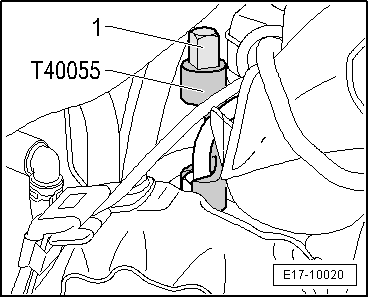
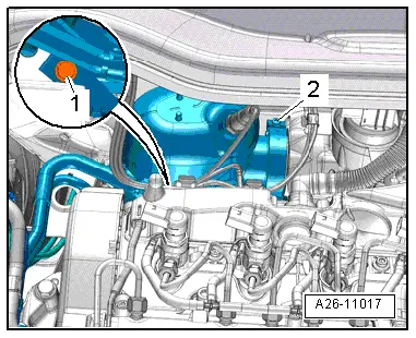
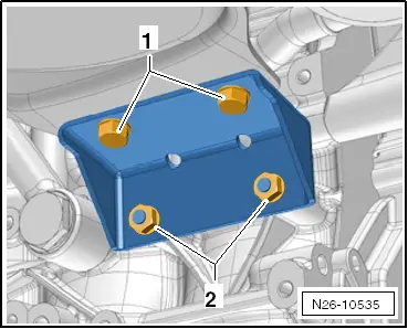
–  Disconnect connector -1-.
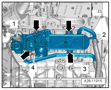
–  Disconnect vacuum hose -4- from the vacuum switch and move clear.
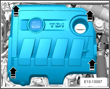
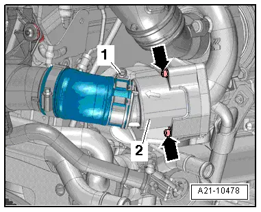
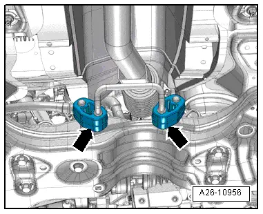
–  Remove bolts -arrows- and detach the radiator for the exhaust gas recirculation.
Installing
Installation is carried out in reverse order, noting the following:
l  Tightening torques → Chapter
  Note
t  Replace the seals, gaskets and self-locking nuts → Electronic parts catalogue.
t  Checking engine oil level → Chapter.
t  Fill up with coolant → Chapter.
t  Secure all hose connections with the correct type of hose clips (same as original equipment) → Electronic parts catalogue.
t  After removing and installing the particulate filter or the pressure differential sender -G505-, the pressure differential sender -G505- must be adapted using the → Vehicle diagnostic tester in all cases. Guided functions; pressure differential sender -G505-: adapting.
l  
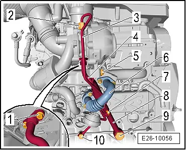
The work procedure must be followed to ensure that the oil supply/return lines together with the turbocharger support are installed tension-free.
l  Furthermore this ensures that the turbocharger support is installed tension-free between crankcase and turbocharger.
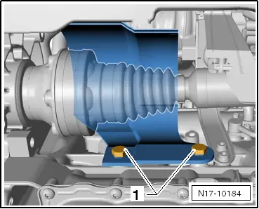
–  Position oil return line on turbocharger together with turbocharger support on turbocharger and crankcase.
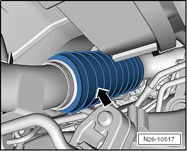
–  Fit oil supply line onto turbocharger and crankcase.
  A26-11015
–  First bring the bolts -1- and the hollow bolt -9- of the exhaust gas turbocharger to the engine block by hand.
–  Fix the screw -5- to the exhaust turbocharger.
–  Then move the banjo bolt -10- and the union nut -2- for the oil supply line.
–  Move the bolt of the combined flange -7- for the oil supply line to the engine block.
–  Finally tighten the bolts -1- and banjo bolt -9- to the engine block and the support of the exhaust gas turbocharger -5- one after another and in several stages to the specified tightening torque → Item. → Item.
–  Tighten banjo bolt of the oil supply line -10- → Item to the specified tightening torque.
  E26-10056
–  Then tighten the union nut of the oil supply line using the socket wrench insert -T40055-, the square ratchet of the torque wrench -VAG 1331--1- and a 13 mm open-ended spanner -SAT 8010/13A-.
–  Finally tighten bolt -7- of the oil supply line / turbocharger support clamp to specified torque.
Tightening torques → Chapter
–  Mount the intake hose on the vibration damper → Chapter.
–  Mount the particle filter → Chapter.
–  Checking engine oil level → Chapter.
–  Check the coolant level.
  E17-10020

Exhaust system (Altea, Altea XL, Leon) > < Lambda probeG39 withheating for the lambda probeZ19 Removing and installing