
Leon Mk1
| Assembly overview - valve gear |

| 1 - | 20 Nm + 1/4 turn (90°) further |
| q | Renew. |
| q | Observe sequence when loosening and tightening → Chapter. |
| 2 - | Rocker arm shaft |
| q | Do not interchange. |
| 3 - | Cylinder head bolt |
| q | Observe sequence when loosening and tightening → Chapter. |
| q | Before installing, insert washers ( → Item) in cylinder head. |
| 4 - | Washer |
| q | For cylinder head bolts. |
| q | Insert in cylinder head before installing bearing caps |
| 5 - | Bucket tappet |
| q | Do not interchange. |
| q | With hydraulic valve clearance compensation. |
| q | Place down with contact surface facing downwards |
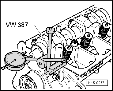
| q | Before installing, check camshaft axial clearance → Fig.. |
| q | Oil contact surface. |
| q | Before removing, remove camshaft bearing caps. |
| 6 - | Valve cotter |
| 7 - | Valve spring plate |
| 8 - | Outer valve spring |
| q | Removing and installing → Chapter. |
| q | With valve spring compressor -2037-, with cylinder head removed |
| 9 - | Inner valve spring |
| q | Removing and installing → Chapter. |
| q | With valve spring compressor -2037-, with cylinder head removed |
| 10 - | Valve stem seal |
| q | Renewing → Chapter. |
| 11 - | Valve guide |
| q | Checking → Chapter. |
| 12 - | Unit injector |
| q | Removing and installing → Chapter. |
| 13 - | Cylinder head |
| q | See note → Chapter. |
| 14 - | Seal |
| q | Do not additionally oil or grease the oil seal sealing lip. |
| q | Before installing, remove residual oil from camshaft journal using a clean cloth. |
| q | To install, mask off groove on camshaft taper (e.g. using Sellotape) |
| q | Removing and installing → Chapter. |
| 15 - | Valves |
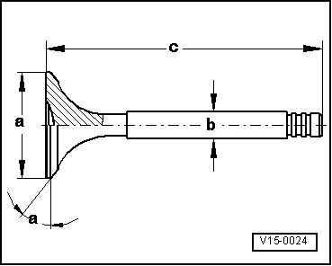
| q | Valve dimensions → Fig.. |
| 16 - | Bearing shell |
| q | Do not interchange used bearing shells (mark). |
| q | Ensure that retaining lugs are correctly seated in bearing caps and cylinder head |
| 17 - | Camshaft |
| q | Checking axial clearance → Fig.. |
| q | Removing and installing → Chapter. |
| q | Check radial clearance with Plastigage, wear limit: 0.11 mm. |
| q | Runout: max. 0.01 mm. |
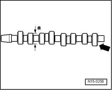
| q | Identification → Fig.. |
| 18 - | Bearing cap |
| q | Installation sequence → Chapter |
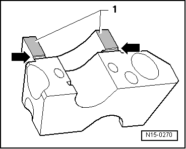
| q | To install, seal parting surfaces of bearing caps 1 and 5 with sealant -AMV 174 004 01- → Fig. |
| 19 - | 8 Nm + 1/4 turn (90°) further |
| q | Renew. |
 Note
Note
|
|
Note
|
|
| Dimension | Inlet valve | Exhaust valve | |
| Ø a | mm | 35.95 | 31.45 |
| Ø b | mm | 6.980 | 6.956 |
| c | mm | 89.95 | 89.95 |
| α | ∠° | 45 | 45 |
|
|