seat Workshop Repair Guides

SEAT Workshop Service and Repair Manuals

Ignition system, glow plug system > < Checking exhaust system for leaks
Removing and installing exhaust gas recirculation system
t  Removing → Anchor
t  Fitting → Anchor
   
Consult the equivalence table for tools and equipment according to applicability among Seat / VW / Audi / Skoda → Chapter.
Special tools and workshop equipment required
t  Hose clamp -3094-, see equivalent → Anchor
t  Wrench kit -3337-, see equivalent → Anchor
t  Torque wrench -VAG 1331-, see equivalent → Anchor.
t  Extractor -VAG 1782-, see equivalent → Anchor
t  Collecting tray -VAS 6208-, see equivalent → Anchor
t  Pliers for spring-loaded band-type clamps -VAS 6499-, see equivalent → Anchor

   
Removing
–  Loosen the engine cover at the locations -arrows- and remove.
  E10-10087
–  Unscrew the securing bolts -arrows- and remove the engine soundproofing..
  E10-0086
–  Remove the connecting line -A-to the cylinder block.
–  Remove air filter housing → Chapter.
  N15-10443
–  Remove crankcase breather hose -1-, press release buttons for this.
–  Unscrew bolt -2-, swing intake hose with intake connection to rear and pull off from turbocharger.
  A21-10437
–  Remove bolts -arrows-.
–  Loosen hose clip -1- and remove pulsation damper -2-.
  A21-10478
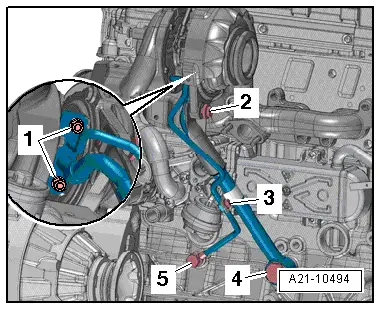
–  Unscrew the bolts -1, 2- and the hollow bolts -4, 5-; rmove the exhaust gas turbocharger bracket together with the oil return hose.
  Note
Disregard -item 3-.
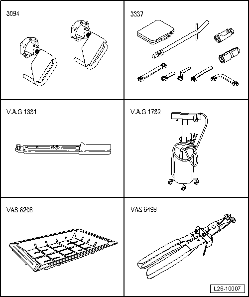
–  Collect the leaking engine oil using the used oil collection and extraction unit -VAG 1782-.
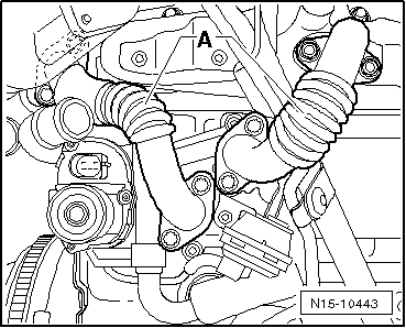
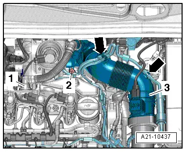
–  Separate the depression flexible hose from the depression box → Item.
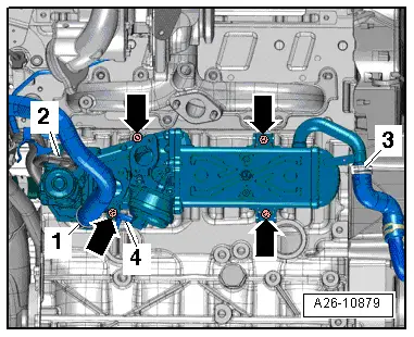
–  Separate the electrical connector of the electrical actuator of the exhaust gas recirculation valve -N18- for the radiator of the exhaust gas recirculation.
–  Connect the coolant supply and coolant return hose on the side of the radiator of the exhaust gas recirculation using the hose clamps up to Ø 25 mm -3094-.
–  Disconnect the coolant supply and coolant return hose from the exhaust gas recirculation system.
–  Collect the leaking coolant using the drip tray for liquids -VAS 6208-.
  A21-10494
–  Unscrews the bolts -arrows- and remove the exhaust gas recirculation system.
Fitting
l  Specified torques → Chapter.
Installation is carried out in the reverse order; note the following:
  Note
t  Always replace the seals, the gaskets and the self-locking nuts → Electronic spare parts catalogue.
t  Checking engine oil level → Chapter.
t  Replenish coolant → Chapter.
t  Secure all hose connections with the correct type of hose clips (same as original equipment) → Electronic parts catalogue.
t  After removing and installing the particulate filter or the pressure differential sender -G505-, the pressure differential sender -G505- must be adapted using the → Vehicle diagnostic, testing and information system VAS 5051 in all cases. Guided functions; pressure differential sender -G505-: adapting.
  A26-10879

Ignition system, glow plug system > < Checking exhaust system for leaks