
Leon Mk1
 Note
Note
|

| 1 - | Conrod bolt: Tighten to 30 Nm and 90° (1/4 turn) further |
| q | Replace |
| q | Oil threads and contact surface. |
| q | Use old bolts when measuring radial clearance |
| q | When measuring radial clearance, tighten to 30 Nm but do not turn further |
| 2 - | Conrod bearing cap |
| q | Mark cylinder number -B- |
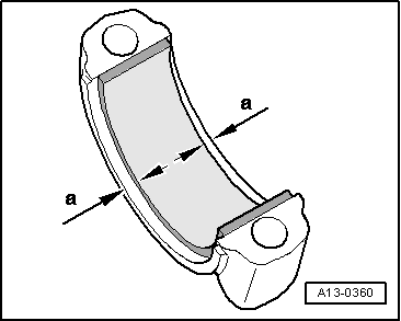
| q | Fitting position: The marks -A- should point towards the pulley |
| 3 - | Bearing shells |
| q | upper bearing shell with oil drilling for piston pin lubrication |
| q | Installation position → Fig. |
| q | Do not interchange used bearing shells (mark). |
| q | New axial play: 0.09 - 8.89 mm; Wear limit: 0.40 mm |
| q | Checking radial clearance with Plastigage: new: 0.020 - 0.061 mm; Wear limit: 0.091 mm. Do not turn crankshaft while measuring radial clearance. |
| 4 - | Conrod |
| q | Can only be replaced as complete unit. |
| q | Mark cylinder number -B- |
| q | Fitting position: The marks -A- should point towards the pulley |
| q | With oil drilling for piston pin lubrication |
| 5 - | Circlip |
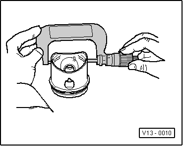
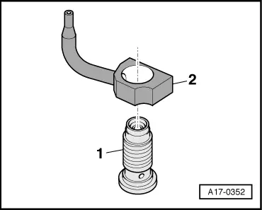
| 6 - | Piston pin |
| q | If difficult to move, heat piston to approx. 60 °C |
| q | Removing and installing with the awl -VW 222A- |
| 7 - | Piston |
| q | Checking → Fig. |
| q | Mark installation position and cylinder number. |
| q | Arrow on piston crown points to pulley end |
| q | Install using piston ring clamp |
| q | Piston and cylinder dimensions → Chapter |
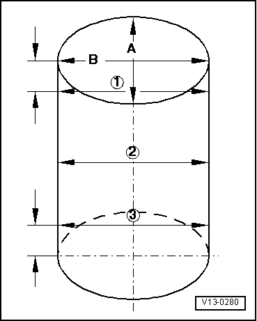
| q | Checking cylinder bore → Fig. |
| 8 - | Piston rings |
| q | compression ring |
| q | Displace the gaps at 120° from each other |
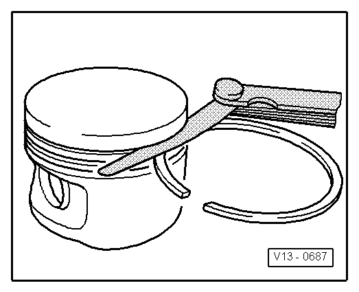
| q | Use piston ring pliers to remove and install |
| q | „TOP“ must face towards piston crown |
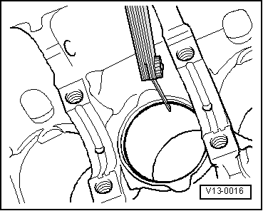
| q | Checking ring gap → Fig. |
| q | Checking ring-to-groove clearance → Fig. |
| 9 - | Piston ring |
| q | Oil scraping ring |
| q | 3-part |
| q | Offset gap of top steel element of piston ring by 120° to next compression ring |
| q | Offset gaps of individual parts of oil scraper ring |
| Piston ring (in mm) | When new | Wear limit |
| Compression rings | 0,20 … 0,40 | 0,80 |
| Steel band ring of oil scraper ring | 0,20 … 0,60 | 0,90 |
|
|
| Piston ring (in mm) | When new | Wear limit |
| Compression rings | 0,06 … 0,09 | 0,20 |
| Oil scraper rings | 0,04 … 0,12 | 0,20 |
|
|
|
|
Note
|
|
|
|