
Leon Mk1
|
 Caution
 Note
Note
|
|
|
|
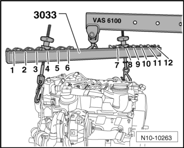
Note
|
|
|
|
| Item | Bolt | Nm |
| 1 → Remark → Remark, 2 → Remark → Remark | M12×55 | 80 |
| 3 → Remark, 4 → Remark | M12×165 | 80 |
| 5 → Remark | M12×105 | 80 |
| 6 → Remark, 7 → Remark | M10×50 | 40 |
| 8 → Remark | M10×70 | 40 |
|
|
|
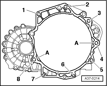
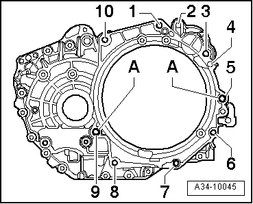
| Item | Bolt | Nm | ||
| 1 1), 3 1), 10 1) | M12x55 | 80 | ||
| 5 1), 9 1) | M12x70 | 80 | ||
| 6 … 8 1) | M10x50 | 40 | ||
| A | Centering handles | |||
| ||||
Note
|
|
|
|
|
Note
|
|
 WARNING
| Component | Nm | |
| Nuts/bolts | M6 | 10 |
| M7 | 15 | |
| M8 | 20 | |
| M10 | 40 | |
| M12 | 65 | |
| Except for the following: | ||
| Direct shift gearbox: Starter motor gearbox | 40 | |
| discrepancies: | ||
| Gearbox support to gearbox. | 60 + 90° → Remark → Remark | |
| Left supercharger air tube to the oil sump | 10 | |
| Pendulum support to gearbox. | 40 + 90° → Remark → Remark | |
| Pendulum support to subframe | 100 + 90° → Remark → Remark | |
| Lock carrier to the bodywork | 10 | |
| Terminal B+ to starter motor | 16 | |
| Earth wire to gearbox | 22 | |
| Front supercharger air tube to the engine block | 22 | |
|