seat Workshop Repair Guides

SEAT Workshop Service and Repair Manuals

Checking hydraulic compensation elements > < Valve guides: verification
Camshaft seal: removing and fitting
t  Removing → Anchor
t  Installing → Anchor
Consult the equivalence table for tools and equipment according to applicability among Seat / VW / Audi / Skoda → Chapter.
   
Special tools and workshop equipment required
t  Hose clamp -3359-, see equivalent → Anchor
t  Hose clamp -T10051-, see equivalent → Anchor
t  Extractor -T10052-, see equivalent → Anchor
t  Camshaft assembly tool -T40094A-,see equivalent → Anchor
t  Puller -T40095-, see equivalent → Anchor
t  Puller -T40096-, see equivalent → Anchor

   
t  Torque wrench (5... 50 Nm) -V.A.G 1331-, see equivalent → Anchor
  W00-0427
t  Torque wrench (40... 200 Nm) -V.A.G 1332-, see equivalent → Anchor
t  Silicone sealant → Spare parts catalogue
t  Electric drill with plastic brush attachment
t  Protective glasses
t  Sealant → Parts Catalogue
  W00-0428
Removing
–  Disconnect the engine cover-arrow-.
–  Remove the injectors → Chapter
–  Remove the common rail (high-pressure reservoir) → Chapter.
–  Detach toothed belt from camshaft and high-pressure pump → Chapter.
–  Remove cylinder head cover → Chapter
  E10-10060
–  Extract the camshaft sprocket bolts -1-.
–  Pull camshaft sprocket off hub.
  N15-0232
–  Lock the hub with the Counterholder -T10051- and unscrew the securing bolts -1- from the hub.
–  Unscrew the securing bolt of the hub with approx. two turns.
  N15-0271
–  Attach the extractor -T10052- and align with openings in hub, tighten mount bolts-1- on hub.
–  Apply tension to hub by evenly tightening puller -2- until hub separates from taper of camshaft.
  Note
During this step, hold the extractor tool with a 30 mm wrench.
–  Remove the hub cone from the camshaft.
–  Remove exhauster pump → Chapter.
  N15-0280
–  Pull off vacuum hose -1-.
–  Unscrew bolts -2- and -4-.
  A21-10306
–  Unscrew the bolts -arrows- and detach the exhaust gas recirculation radiator.
  Note
Do not disconnect the coolant hoses -1- and -2-.
  A21-10307
–  Unscrew bolts-Arrows- and remove mount for exhaust gas recirculation cooler.
  A26-10681
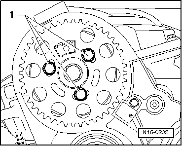
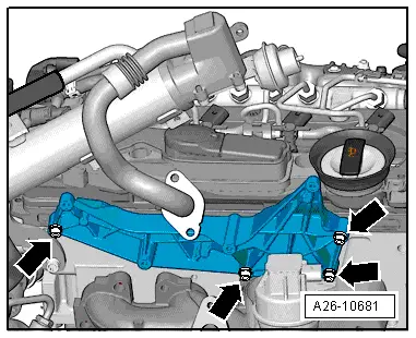
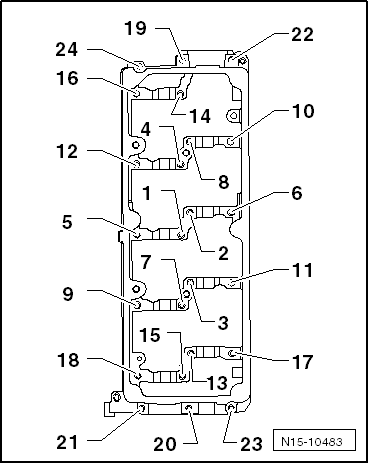
–  Unscrew the securing bolts of the bearing cap module in the following sequence: -24 ... 1-.
–  Remove the bearing cap module.
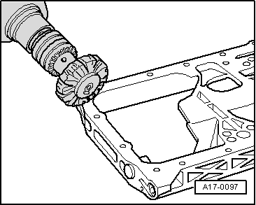
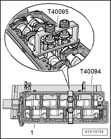
–  Take out camshafts carefully.
Installing
  Note
t  
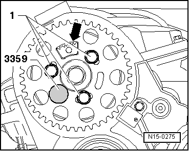
When installing the camshafts, the cams of cylinder 1 should be pointing upwards.
t  Do not interchange used bearing shells (mark).
t  When fitting the camshaft, ensure that the securing lugs of the half bearing in the bearing cap module and cylinder head are correctly seated.
t  
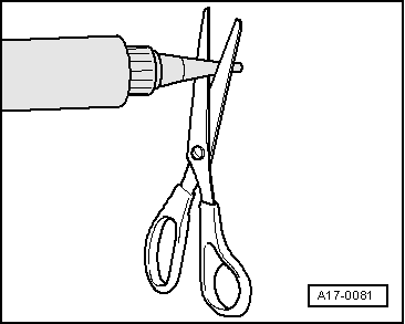
Seal the contact surface between the bearing cover module and the cylinder head using silicone → Spare parts catalogue.
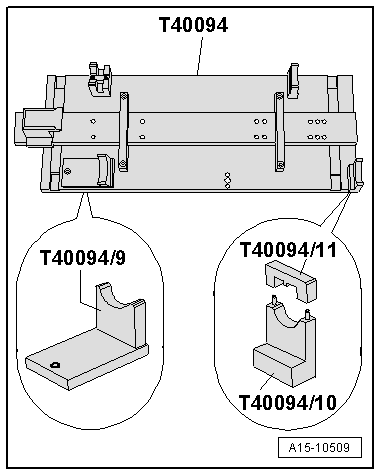
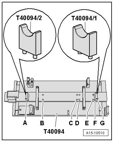
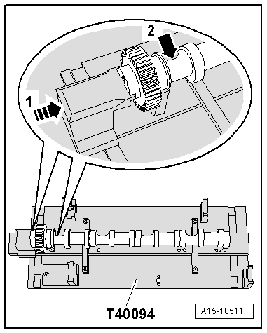
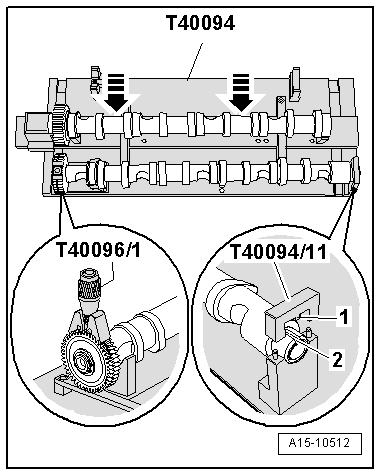
  Caution
The camshafts may be attached as described below and only with the Camshaft fitting tool -T40094A-. Otherwise the axial bearings of the bearing cap module could be damaged, as a result of which the cylinder head would have to be replaced.
  N15-10421
–  Remove the remaining sealant from cylinder head and retaining frame using rotating plastic brush or similar.
  Caution
Ensure that there are no sealant remnants on the cylinder head and on the bearings.
–  Clean sealing surfaces; they must be free of oil and grease.
–  Oil the camshaft contact surfaces.
  A17-0097
Set up camshaft fitting tool -T40094- as follows:
–  Secure supports -T40094/9- and -T40094/10- (with -T40094/11-) to base plate, as shown in the figure. If necessary, remove the supports screwed on here.
  A15-10509
–  Fit support -T40094/1- onto position -F- and support -T40094/2- onto position -A-.
  A15-10510
–  Place inlet camshaft in supports -T40094/1- and -T40094/2-.
–  Turn inlet camshaft in such a way that it can be locked in TDC position using locking device -arrow 1-.
l  Recess -arrow 2- for cylinder head bolt must face outwards.
  A15-10511
–  Place exhaust camshaft in supports -T40094/9- and -T40094/11-.
–  Lock exhaust camshaft with top section -T40094/11-.
l  The lug -1- on the top section must engage in the slot -2- in the camshaft,
–  Place clamping tool -T40096/1- on the splines of the exhaust camshaft in such a way that each side of the tensioning tool engage on the two halves of the gear.
l  The wider arm must engage in the wider half of the gear.
–  Tighten the clamping tool using the knurled wheel so that the faces of the gear teeth are in alignment.
–  Slide inlet camshaft towards exhaust camshaft, until gear teeth engage -arrows-.
  A15-10512
–  Fit retaining frame on camshafts.
l  All camshaft bearings must be seated on the camshafts.
–  Position camshaft fitting tool -T40095- and fix camshafts in position in retaining frame, as shown in illustration.
–  Detach top section -T40094/11-.
  A15-10154
–  Cut off tube nozzle at upper marking (nozzle Ø: approx. 2 mm).
–  Apply 2-3 mm wide sealant beads on the clean sealing surfaces of the cylinder head, as shown in the ill.
  Note
  A17-0081
The sealant beads may not be thicker, since excess sealant can otherwise get into the camshaft bearing.
–  Take the camshafts together with retaining frame, camshaft insert tool -T40095- and clamping tool -T40096/1- out of the camshaft insert tool -T40094- and insert components carefully into cylinder head.
  N15-10422
–  Unscrew the securing bolts of the bearing cap module in the sequence -1 ... 24- tighten manually.
l  The retaining frame must be supported on the entire surface on the cylinder head.
–  Unscrew the securing bolts of the bearing cap module in the sequence -1 ... 24- tighten to the final torque. Tightening torque: 10 Nm
–  Remove the insert tool -T40095- and the Tensioner -T40096/1-.
–  Replace the seal of the camshaft → Chapter.
–  Use a new cover together with a suitable driver → Item.
Further assembly is carried out in the reverse order, note the following:
  Note
t  After installing the camshaft do not start engine for approx. 30 minutes. Hydraulic compensation elements must be set. (Else the valves fit on the pistons).
t  After working on valve gear, carefully crank engine at least 2 revolutions by hand to ensure that no valves make contact on starting.
–  Fit the camshaft hub.
  N15-10483
–  Tighten hub securing bolt -1- to 100 Nm. To do this, use the retention tool -T10051-.
  N15-0271
–  Move the camshaft wheel onto the hub.
  Note
The cogged part -arrow- of the camshaft cogwheel should face upwards.
–  Align camshaft sprocket centrally in elongated holes.
–  Hand-tighten securing bolts -1- on camshaft sprocket so that there is no play.
–  Immobilise the hub using the retention tool -3359-.
–  Install toothed belt and adjust the valve timing → Chapter.
–  Install the vacuum pump → Chapter.
–  Install cylinder head cover → Chapter.
  N15-0275

Checking hydraulic compensation elements > < Valve guides: verification