seat Workshop Repair Guides

SEAT Workshop Service and Repair Manuals

Valve control > < Engine: assembly and dismantling
Removing and installing cylinder head
t  Removing → Anchor.
t  Installing → Anchor.
Consult the equivalence table for tools and equipment according to applicability among Seat / VW / Audi / Skoda → Chapter.
   
Special tools and workshop equipment required
t  Spanner -T10070-, see equivalent → Anchor
t  Extractor -T40039-, see equivalent → Anchor
t  Torque wrench -V.A.G 1331-, see equivalent → Anchor.
t  Torque wrench -V.A.G 1332-, see equivalent → Anchor.
t  Pliers for spring-loaded band-type clamps -VAS 6499-, see equivalent → Anchor
t  Tray -VAS 6208-, see equivalent → Anchor

   
t  Hose clamp -3036-, see equivalent → Anchor
  W00-0270
t  Extractor -T40001-, see equivalent → Anchor
Removing
l  Engine installed.
  Note
t  All cable ties which were opened or cut during removal must be renewed at the same points.
t  Carry out an engine oil change if this is dirty → Booklet301.
t  When using sealing products, follow current recommendations → ETKA (electronic parts catalogue)
–  Refer to coding on vehicles with encoded radio/radio navigation system (RNS); obtain coding if necessary.
  W00-10104
–  Pull off engine cover panel -arrows-.
  WARNING
Hot vapour/hot coolant may escape when opening expansion tank. Cover cap with cloth and open carefully.
–  Open cap on coolant expansion tank.
  E10-10062
–  Release quick-fasteners -1- and -2- and take off front noise insulation.
–  Drain coolant → Chapter.
–  Remove toothed belt → Chapter.
  A10-1320
–  Loosen the sprocket of the cam shaft with the counter holder -3036-.
  A13-0381
–  Release the camshaft sprocket with the extractor -T40001-, the claw -T40001/6- and the claw -T40001/7-.
–  Separate the rear toothed belt protection from the cylinder head → Item.
  A15-0771
–  Unscrew earth connection -1-.
–  Disconnect vacuum hose going to brake servo at bulkhead -2-.
–  Disconnect ACF hose -3-.
  A10-10319
–  Disconnect coolant hoses -1 and 2- and detach coolant expansion tank -arrow-.
–  Separate the connector of the switch for coolant shortage indicator -F66- below on the coolant compensation tank.
  A10-10321
–  Unplug electrical connector from charge air pressure sender -G31--1-.
–  Remove charge air hose (left-side) -2-.
  A10-10320
–  Detach air intake hose -1- going to turbocharger (bottom right).
–  Separate the air hose to the charged air cooler at the lock carrier -2-.
  A10-10311
–  Detach electrical connectors -1 and 2- and move wire clear.
  A10-10316
–  Unscrew oil supply pipe for turbocharger at cylinder block -1-
–  Unscrew bolt -2- of support for turbocharger.
  A21-10081
–  Remove oil supply pipe for turbocharger -arrows-.
  A21-10082
–  Remove the oil return line -arrows- from the exhaust turbocharger.
  A21-10079
–  Loosen bolt -1- of support for turbocharger 2 turns.
–  Remove intake manifold → Chapter.
–  Remove catalytic converter → Chapter.
–  Remove cylinder head cover → Chapter
  A21-10085
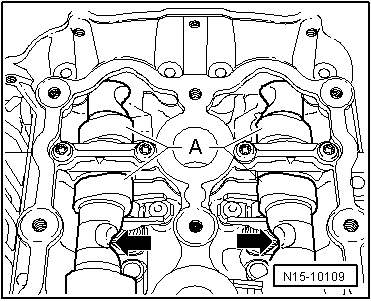
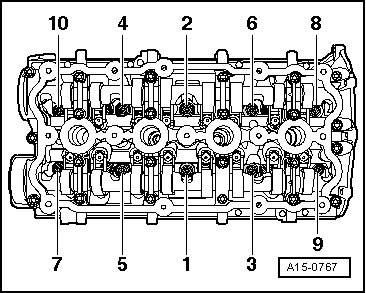
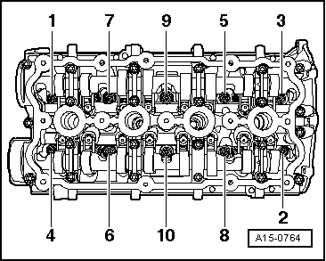
–  Loosen the cylinder head bolts in the specified order.
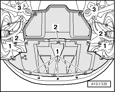
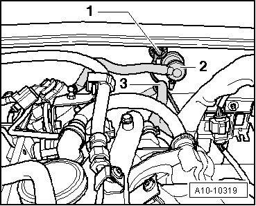
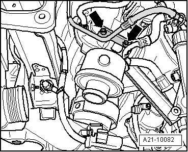
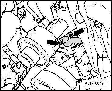
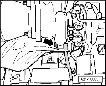
  Note
Check that all hose and line connections between engine, gearbox and body have been detached.
–  Remove the cylinder head.
Installing
  Note
t  Renew the cylinder head bolts.
t  On assembling, replace self-locking nuts, bolts subject to goniometric tightening, as well as o-rings and gaskets.
t  Secure the joints between hoses by using the same clamps as originally fitted → Spare parts catalogue
t  
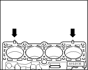
If repairing, carefully remove any remains of gasket material from the cylinder head and cylinder block. See that it does not cause any grooves or scratches.
t  Carefully remove any remaining emery and abrasive material.
t  Do not remove new cylinder head gasket from packaging until it is ready to be fitted.
t  Handle gasket extremely carefully. Damaging the silicone layer or the indented area will lead to leaks.
t  No oil or coolant must be allowed to remain in the blind holes for the cylinder head bolts in the cylinder block.
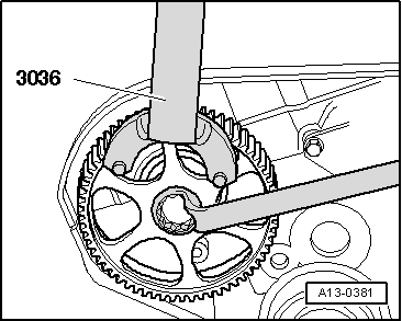
t  For high-temperature paste refer to → Parts catalogue.
  WARNING
The engine must only be rotated by turning the crankshaft in the normal rotation direction (clockwise).
  Note
The engine should revolve around the central bolt of the crankshaft.
  A15-0764
–  Make the mark on the camshaft sprocket and the mark on the notched belt guard coincide. The recesses -arrows- point only vertically upwards.
–  If crankshaft has been rotated in the meantime: set the piston of the 1st cylinder to top dead centre (TDC) and then turn crankshaft back slightly.
  N15-10109
–  Place cylinder head gasket in position.
t  Note position of centring pins in cylinder block -arrows-.
t  Observe correct installation position of the cylinder head gasket. Identification: The TDC No. must be legible from the inlet side.
–  Fit cylinder head.
–  Insert new cylinder head bolts and tighten hand-tight.
  A15-0135
–  Tighten the cylinder head in 2 stages, in the following tightening sequence:
Tightening torque for the cylinder head bolts:
  A15-0767
stage:Tighten
1
–  Tighten to 40 Nm using a torque key.
2
–  Turn 90° (1/4 turn) further using a rigid wrench.
3
–  Turn 90° (1/4 turn) further using a rigid wrench.

  Note
Cylinder head bolts do not have to be torque down again later after repair work.
–  Install cylinder head cover → Chapter.
–  Install toothed belt → Chapter.
–  Install poly V-belt → Chapter.
–  Electrical connections and routing → Current flow diagrams, Electrical fault finding and Fitting locations.
–  Installing intake manifold → Chapter.
–  Connect battery → Electrical system; Rep. gr.27.
–  Check oil level . → Chapter.
–  Fill up with coolant → Chapter.
  Note
t  The drained coolant can only be reused if the cylinder head or the cylinder block have not been replaced.
t  Contaminated or dirty coolant must not be used again.
–  Assemble the lock carrier with attachments → Bodywork - Exterior assembly work ; Rep. gr.50.
   
–  The torque reaction support must set itself on its rubber stop by means of its self weight, then tighten the nuts -arrows-.
–  Fit the front bumper cover → Exterior body installation work; Rep. gr.63.
–  Check headlight adjustment → Booklet301.
  WARNING
Do not use charger for boost starting, The control units of the vehicle may be damaged.
Tightening torques
  A10-10298
Components: Nm
Bolts/nutsM610
 M820
Front exhaust pipe to turbocharger30 → Remark2)
Cylinder head cover to cylinder head10
Notched belt guard to engine block10 → Remark
Battery terminal to battery pole6

1)  Coat the exhaust manifold studs and Lambda probe threads with high-temperature paste; High-temperature paste → Parts catalogue
2)  Install using locking fluid → Parts catalogue
   

Valve control > < Engine: assembly and dismantling