seat Workshop Repair Guides

SEAT Workshop Service and Repair Manuals

Engine lubrication > < Removing and installing cylinder head
Camshaft seal: removing and fitting
t  Removing → Anchor.
t  Installing → Anchor.
Consult the equivalence table for tools and equipment according to applicability among Seat / VW / Audi / Skoda → Chapter.
Special tools and workshop equipment required
   
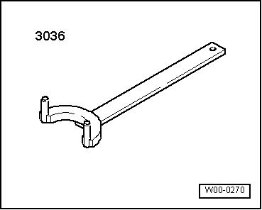
t  Hose clamp -3036-, see equivalent → Anchor
  W00-0270
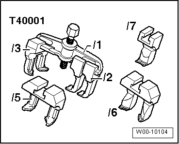
t  Extractor -T40001-, see equivalent → Anchor
Removing
  Note
t  Sealing surfaces at bottom of retaining frame and top of cylinder head may not be machined.
t  The camshaft bearings are integrated into the cylinder head and retaining frame. Toothed belt must be slackened before removing retaining frame.
t  Renew camshaft oil seal and sealing cap if retaining frame has been unfastened.
–  Remove the variator → Chapter.
–  Remove toothed belt → Chapter.
  W00-10104
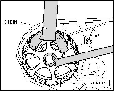
–  Loosen the sprocket of the cam shaft with the counter holder -3036-.
  A13-0381
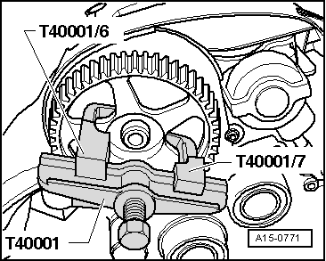
–  Release the camshaft sprocket with the extractor -T40001-, the claw -T40001/6- and the claw -T40001/7-.
–  Separate the rear toothed belt protection from the cylinder head.
–  Loosen retaining frame bolts evenly working from outside inwards and remove retaining frame.
–  Carefully lift out the camshafts and place them down on a clean surface.
  A15-0771
–  Remove old sealant residues from the slot of the upper bridge and from the sealing faces.
–  Prevent dirt and sealant remains from entering the cylinder block.
Installing
  Note
t  The contact surfaces must be free from oil and grease.
t  Pistons must not be at TDC.
t  See that the roller rams rest properly on the valve stem ends.
–  Oil the camshaft running surfaces.
  N15-10105
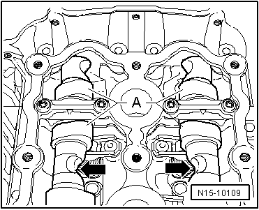
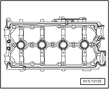
–  Insert camshafts carefully in the camshaft bearings of cylinder head. Cams -A- of cylinder 4 must face each other.
  N15-10109
–  Apply a uniform and slightly raised sealant grub in the clean slot of the top bridge → Parts catalogue. Distribute sealant evenly on sealing surface.
  Note
t  The sealant must not be applied too thickly. Remove excess sealant with a cloth that does not fray.
t  The assembly and bolting of the top bridge must be carried out without interruption, as the sealant hardens up as soon as the sealing faces are in mutual contact.
t  Note the use-by date of the sealant.
  N15-10105
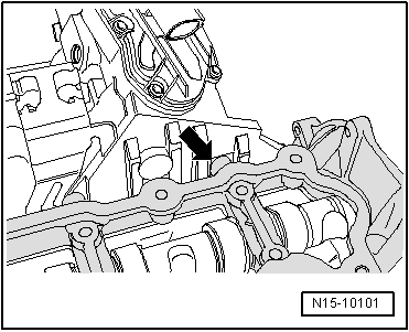
–  Set the top bridge such that it reaches the exhaust return valve -N18--arrow-.
–  Tighten the screws from inside outwards lightly and in several steps.
  N15-10101
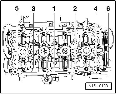
–  Then tighten bolts in the sequence indicated to 8 Nm.
–  Fit cover → Item with pressure tool -3334- 1... approx. 2 mm
–  Fit the camshaft seal → Chapter.
–  Install toothed belt cover (rear).
–  Fit the spring buckle in the camshaft.
  N15-10103
–  Mounting the cam shaft sprocket. To tighten the bolt, immobilise the camshaft sprocket with the counterhold -3036-. Tightening torque: 65 Nm.
  Note
t  When turning the camshaft, the pistons must not be at TDC. Otherwise there is a risk of damage to valves and pistons.
t  Ensure correct seating of the centring spring.
–  Install toothed belt → Chapter.
–  Fitting the variator → Chapter.
–  Install cylinder head cover → Chapter.
–  Assemble the lock carrier with attachments → Bodywork - Exterior assembly work ; Rep. gr.50.
  A13-0381
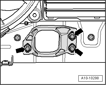
–  The torque reaction support must set itself on its rubber stop by means of its self weight, then tighten the nuts -arrows-.
–  Fit the front bumper cover → Exterior body installation work; Rep. gr.63.
–  Check headlight adjustment → Booklet301.
Installation is done in the reverse order.
Tightening torques
Valve control: assembly overview → Chapter.
Assembly overview - cylinder head → Chapter.
  A10-10298

Engine lubrication > < Removing and installing cylinder head