
Leon Mk1
|
|
|
|
|
|
|
|
|
|
|
|
|
|
|
|
|
 WARNING
|
|
|
|
 Note
Note
|
|
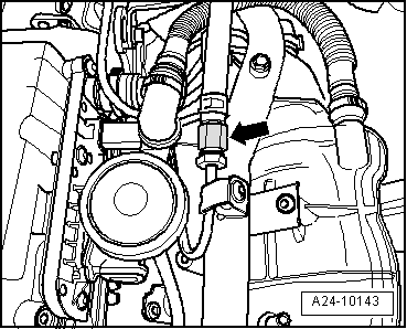
| Components: | Nm |
| Fuel line for fuel distributor line | 22 |