seat Workshop Repair Guides

SEAT Workshop Service and Repair Manuals

Checking fuel pump delivery > < Checking fuel pump
Fuel pump control unitJ538: check
Fuel pump control unit -J538-: check
Consult the equivalence table for tools and equipment according to applicability among Seat / VW / Audi / Skoda → Chapter.
   
Special tools and workshop equipment required
t  Manual multimeter -VAG 1526C-, see equivalent → Anchor
t  Auxiliary cable kit -VAG 1594C-, see equivalent → Anchor
t  Engine unit tester -VAG 1598/39-, see equivalent → Anchor
t  Test box with (105) pins -VAG 1598/42-, see equivalent → Anchor

Test prerequisites
l  Battery voltage min. 12.5 V
   
l  Fuse in fuse holder -S228- (position 28) OK.
l  Ignition switched off
Checking voltage supply for fuel pump (from fuel pump control unit -J538-)
–  Remove the luggage compartment cover.
–  If necessary, fold forward right backrest of rear seat bench.
  A97-0242
–  Loosen the bolts -arrows- and remove the fuel delivery unit.
  A20-0774
–  Press back the protective sleeve.
–  Connect the hand multimeter -VAG 1526C- with measurement needles and connectable adapters from theauxiliary measurement kit -VAG 1594C- between sockets -1- and -4-, -V.A.G 1594 A-as shown in the illustration. The connector remains connected.
  Note
The connector contacts are numbered accordingly on the rear of the connector.
–  Start engine.
l  Specified value on starting and when idling: 4 ... 5.7 V.
–  Actuate the gas pedal in jerks and release again (short gas supply).
l  Specification: The voltage reading should rise at first, then fall and finally increase to the previous reading.
If the reading is not as described:
–  Check the supply voltage and the excitation of the control unit for fuel pumps -J538-.
  A20-1142
Fuel pump control unit -J538- : check supply voltage
–  Remove the connector -arrow- from the fuel pump control unit -J538-.
  A20-1269
–  Connect multimeter between contacts -3- and -4- of connector to measure voltage.
–  Switch on the ignition.
l  Specification: approx. battery voltage
If specification is not obtained:
–  Use current flow diagram to eliminate open circuit in wiring.
  A28-0020
Fuel pump control unit -J538-: Checking activation
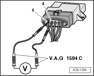
–  To check voltage, connect the multimeter with measurement needles and connectable adapters from theauxiliary measurement kit -VAG 1594C- between sockets -4- and -5-, as shown in the illustration. The connector remains connected.
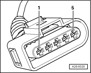
  Note
The connector contacts are numbered accordingly on the rear of the connector.
–  Start engine.
l  Specified value when starting and when idling: Approx. 5.0 Volt.
–  Actuate the gas pedal in jerks and release again (short gas supply).
l  Specification: The voltage reading should rise at first, then fall and finally increase to the previous reading.
  A20-1264
If the reading is not as described:
–  Turn the ignition off.
–  Connect the test box -V.A.G 1598/42- with the adapter cable -V.A.G 1598/39-1- or the adapter cable -V.A.G 1598/39-2- to the cable harness. The engine control unit is not connected. Connect earth clip of test box to negative terminal of battery.
  Caution
To avoid damaging electronic components, select the appropriate measuring range before connecting the test leads and observe the test conditions.
  A24-0622
–  Check for breaks, shorts to earth or battery positive in the following wiring connection:
  A28-0020
Connector
Contact
Test box with (105) pins -VAG 1598/42-
, socket
-5-B 27

–  Repair the cable break or short-circuit according to the circuit diagram.
If no fault is found:
–  Replace the fuel pump control unit -J538-.
   

Checking fuel pump delivery > < Checking fuel pump