
Leon Mk1
|

| Special tools and workshop equipment required |
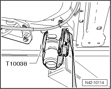
| t | counterhold -T10038-, see equivalent → Anchor |
| t | Torque wrench (5 - 50 Nm) -V.A.G 1331-, see equivalent → Anchor |
| t | Engine and gearbox crane -V.A.G 1383 A-, see equivalent → Anchor |
|
 Caution
|
|
|
|
|
|
|
|
 Note
Note
|
|
|
|
 WARNING
|
|
|
|
|
|
|
|
|
|
Note
|
|
|
|
|
|
|
|
| Components: | Nm |
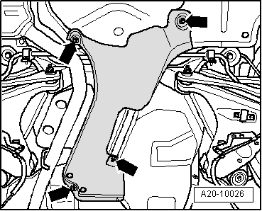
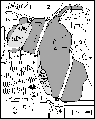
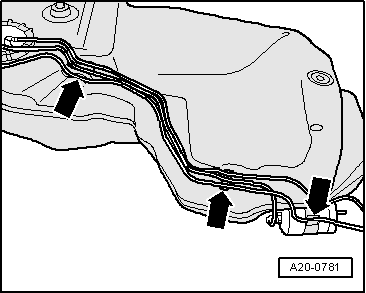
| Securing straps to body | 23 |
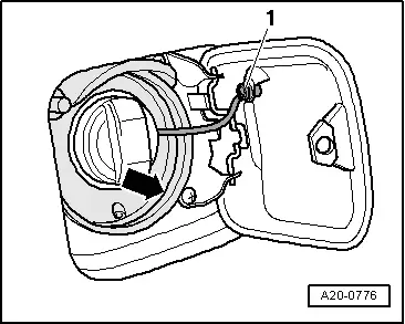
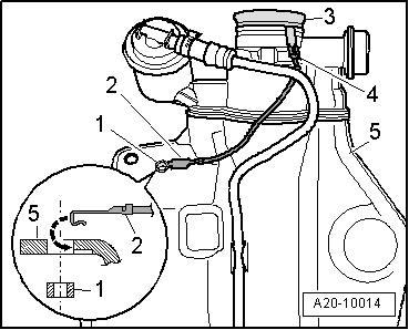
| Fuel filler neck to the wheel housing | 23 |