seat Workshop Repair Guides

SEAT Workshop Service and Repair Manuals

Mixture preparation system, electronic inj.,Gas > < Charge air system
Adjusting vacuum unit for turbocharger
  Note
The vacuum unit must only be adjusted when the linkage has been loosened.
   
Special tools and workshop equipment required
t  Pressure limiting valve -VAS 6342-
t  Dial gauge set, 4-part -VAS 6341-
t  Hand vacuum pump -VAS 6213-
t  Turbocharger tester -V.A.G 1397A-
t  Universal dial gauge bracket -VW 387-
t  Dial gauge extension, 30 mm -VAS 6341/3- (not shown)
t  Flat pickup -VAS 6341/4- (not shown)

Operation process
   
–  Lift engine cover panel at points -1- and pull it forwards in direction of -arrow-.
  N10-10281
–  Unbolt heat shield over turbocharger -arrows-.
–  Open and close expansion tank cap to release pressure in cooling system.
–  Now drain coolant.
  Note
Pull coolant hoses off engine with hose clip pliers -VAS 6340-.
  N21-10220
–  Pull off connecting hoses -1- and coolant hoses -3-.
–  Remove bolts and securing nuts -4- from turbocharger.
  N21-10065
–  Unscrew securing bolt -2- and remove upper coolant pipe.
  Note
The lower coolant pipe can only be removed following the removal of the catalytic converter.
–  Unscrew bolts -1- and remove pressure pipe.
–  Remove noise insulation → General body repairs, exterior; Rep. gr.50.
Continuation for all vehicles
–  Remove wiring for Lambda probe after catalytic converter -G130- and for alternator from cable guides -arrows-.
  N21-10081
–  Pull connector off Lambda probe after catalytic converter -G130- and remove.
  N21-10066
–  Open hose clip -3- and remove charge air pipe -2-.
–  Unbolt exhaust pipe from catalytic converter -arrows-.
–  Remove catalytic converter downwards.
–  Pull hose -arrow- from vacuum unit on turbocharger.
Checking vacuum unit adjustment → Chapter.
Continuation if the vacuum unit has been renewed or the linkage loosened
–  Remove sealing paint from lock nut -2-.
  N21-10067
–  Pull off retaining clip -1- and loosen lock nut -2- on vacuum unit linkage.
  N21-10119
–  Pre-adjust bypass flap -2- on vacuum unit linkage -1- via knurled screw, so that bypass flap can just be turned by hand.
–  Turn knurled nut -1- 2 turns further.
–  Tighten lock nut hand-tight.
  N21-10120
–  Connect up hand vacuum pump -VAS 6213-, turbocharger tester -V.A.G 1397A- to connection -II- and pressure control valve -VAS 6342- as shown in illustration.
–  Close pressure control valve -VAS 6342- at lever -2-.
–  Push sliding ring -1- on hand vacuum pump -VAS 6213- to pressure gauge in direction of -arrow-.
–  Switch on turbocharger tester -V.A.G 1397A- and set sliding switch to position -II-.
  N21-10125
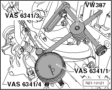
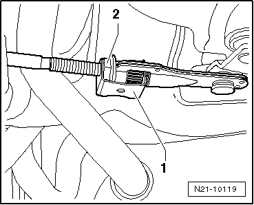
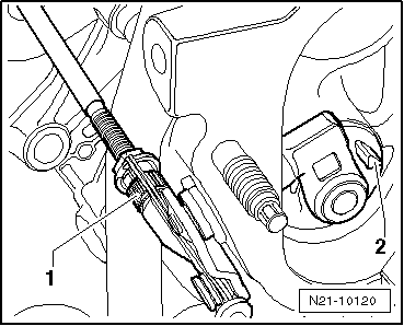
–  Secure universal dial gauge bracket -VW 387- to turbocharger.
  Note
The dial gauge linkage and the vacuum unit linkage must align.
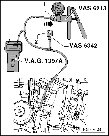
–  Secure dial gauge -VAS 6341/1- with dial gauge extension, 30 mm -VAS 6341/3- and flat pickup -VAS 6341/4- to universal dial gauge bracket -VW 387-.
–  With pressure at 0 bar, set dial gauge -VAS 6341/1- to 1 mm preload.
–  Operate hand vacuum pump -VAS 6213- until a pressure of 800 mbar is displayed on turbocharger tester -V.A.G 1397A-.
–  Vent system via pressure control valve -VAS 6342- so that pressure reading drops to 0 mbar.
–  Repeat this procedure approx. 3-5 times.
  Note
This procedure is intended to prevent the vacuum unit bypass flap or linkage from jamming.
  Note
The dial gauge values (mm) listed here include the 1 mm preload that is initially set on the gauge.
–  Vent system via pressure control valve -VAS 6342- so that pressure reading drops to 0 mbar.
–  Set dial gauge -VAS 6341/1- to 0.
  Note
t  The following measurements must be performed in continuous sequence. Do not allow the pressure to drop to 0 between measurements.
t  Do not knock against linkage throughout the entire measurement procedure.
–  Operate hand vacuum pump -VAS 6213- until turbocharger tester -V.A.G 1397A- indicates 500 +/- 5 mbar.
–  Read off and note value indicated on dial gauge -VAS 6341/1-.
–  Operate vacuum pump -VAS 6213- until turbocharger tester -V.A.G 1397A- indicates 800 +/- 5 mbar.
–  Vent system via pressure control valve -VAS 6342- so that pressure reading drops to 500 +/- 5 mbar.
–  Read off and note value indicated on dial gauge -VAS 6341/1-.
–  Add values 1 and 2 together and divide by 2.
–  The result (mean value) should be 5.5 +/- 0.25 mm.
–  Correct setting if the result (average) is not 5.5 +/- 0.25 mm, tighten lock nut hand-tight and repeat measurement.
–  If the result (mean value) is 5.5 +/- 0.25 mm, tighten the lock nut to 9 Nm and secure with sealing paint.
–  Secure retaining clip to vacuum unit linkage.
Installation is carried out in the reverse order. When installing, note the following:
t  Renew seals, gaskets and self-locking nuts.
t  
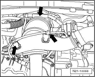
Hose connections and hoses for charge air system must be free of oil and grease before assembly.
t  Secure all hose connections with the correct type of hose clips (same as original equipment).
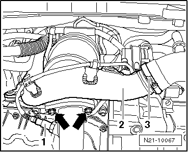
t  If renewed, place seal in groove of charge air hose. Ensure seal is correctly seated in groove.
t  Lightly moisten seal with engine oil.
  N21-10121
t  Bring retaining clip to release position -arrow-.
t  When installing air pipes with plug-in connector, ensure that securing clip -arrow- audibly engages into retaining lug -A-.
  Caution
The screw-type clips on the charge air pipes must be tightened to 5.5 Nm. If the torque is too low or too high, the charge air hose may slip off the charge air pipe during vehicle operation.
Assembly overview - turbocharger → Chapter.
Assembly overview - charge air system → Chapter
Removing and installing parts of exhaust system → Chapter
  N21-0184

Mixture preparation system, electronic inj.,Gas > < Charge air system