seat Workshop Repair Guides

SEAT Workshop Service and Repair Manuals

Engine lubrication > < Valve stem seals: replacing
Cylinder head: removing and fitting
t  Removing → Anchor
t  Fitting → Anchor
t  Torque values → Anchor
Consult the equivalence table for tools and equipment according to applicability between Seat / VW / Audi / Skoda → Chapter.
   
Special tools and workshop equipment required
t  Pliers -SAT 1105-, see equivalent → Anchor
t  Torque wrench kit -SAT 8010-, see equivalent → Anchor
t  Puller -T10029-, see equivalent → Anchor
t  Centre guide -T20049-, see equivalent → Anchor
t  Wrench -T20079A-, see equivalent → Anchor
t  Tray -T20173-, see equivalent → Anchor

   
t  Socket -T10358-, see equivalent → Anchor
  W00-10513
t  Socket -U 30025E-, see equivalent → Anchor
t  Step ladder
Removing
  Note
t  To perform these tasks, the battery earth strap must be removed. Therefore, you must check whether the vehicle has a coded radio. If so, refer to the anti-theft coding.
t  All the cable fixings that are opened or cut during removal of the cylinder head must be fitted in the same position when reinstalling the engine.
–  With ignition switched off, disconnect battery earth strap.
–  Place the drip tray -T20173- under the engine.
–  Drain coolant → Chapter.
–  Remove the upper part of the inlet manifold → Chapter.
  Note
Cover the intake channels of the lower intake manifold element using a clean cloth.
  WARNING
Fuel system is under pressure! Before opening the system, place a cloth around the connection. Then release pressure by carefully loosening the connection.
  W00-2961
–  Remove the flexible feed and return pipes -1- and -2- running to the fuel rail by pressing the locking pins.
–  Remove the electrical connection -3- from the Hall sender -G40-.
–  Remove the electrical connections -4- from the injectors -N30- … -N33-, unclip the cable strip -5- and release the wiring harness.
–  Remove the following connectors:
t  Spark plugs (use puller -T10029-)
t  Coolant temperature sender -G62-
t  Lambda probe before catalytic converter -G39-
–  Release the cylinder head coolant hose.
–  Unscrew the fastening bolts from the connection nozzle → Item and remove it.
  E15-0255
–  Unscrew the fastening bolts -arrows- and remove the engine noise damping cover.
  N10-10175
–  Unscrew the right-hand noise damping -fastening points 1 ... 3-.
–  Remove the exhaust manifold mount and unscrew the front exhaust pipe with catalytic converter .
–  Remove the ribbed-belt → Chapter.
  A10-1643
–  Unscrew the bolts -arrows- and remove the Poly V-belt tensioner.
–  Remove the upper toothed belt guard
–  Removing notched belt → Chapter
–  Removing the cylinder head cover → Chapter.
–  Unscrew the upper bolt on the rear timing belt guard → Item.
  A13-0374
–  Unscrew the attachment bolt for the gearbox and tighten the support -T10358-, as shown in the figure.
–  Fit the hooks of the support device -U 30025E- to the bracket -T10358-, as shown in the figure.
–  Turn the spindle until the hooks are slightly tightened.
  E15-10077
–  Release the hook -1- from the left ring and move the spindle to the left of the mounting support -U 30025E-.
  Note
For cylinder heads with polydrive bolts, use the wrench -T20079A-.
  E15-10078
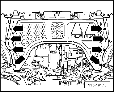
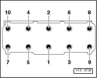
–  Loosen the cylinder head bolts in the order given and then remove them.
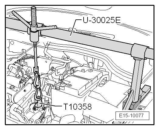
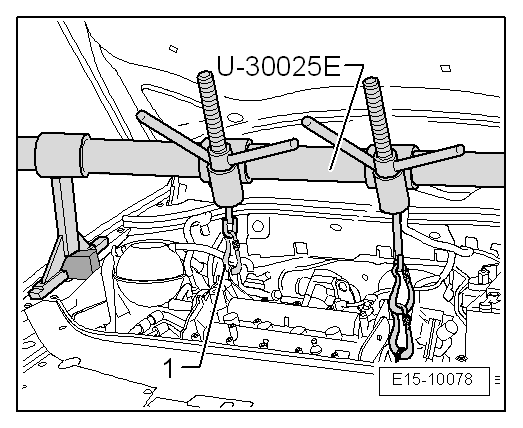
–  Lift the cylinder head out with the help of a second mechanic.
–  Place the cylinder head on a soft surface with the combustion chamber side facing up.
Fitting
  Note
t  Carefully remove any remains of sealant from the cylinder head and cylinder block. Ensure that no scoring or scratching is produced.
t  Carefully remove any remaining emery and abrasive material.
t  No oil or coolant must be allowed to remain in the blind holes for the cylinder head bolts in the cylinder block.
t  The hoses must be free of oil and grease before fitting.
t  Renew cylinder head bolts.
t  When fitting, replace the self-locking nuts and bolts.
t  Renew bolts which have a specified tightening angle, as well as seals and gaskets.
t  Do not remove the new gasket from its packaging until just before fitting.
t  Handle gasket extremely carefully. Damaging the silicone layer or the indented area will lead to leaks.
t  When fitting a new cylinder head with the camshafts fitted, the contact surfaces between the roller rocker arms and the cam contact surfaces must be oiled following the fitting of the cylinder head.
t  The plastic protectors fitted to protect the open valves should not be removed until the cylinder head is ready to be fitted.
t  Secure all hose connections with the correct hose clips (same as original equipment) → Parts catalogue.
t  
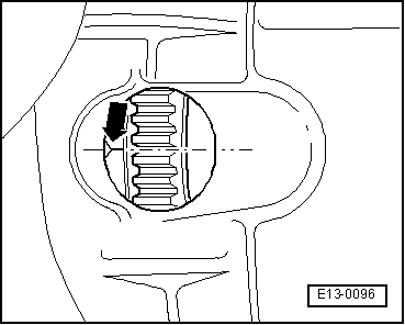
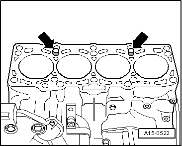
Before fitting the cylinder head, locate crankshaft at TDC, cylinder 1.
–  Place a clean cloth in cylinders so that no dirt or particles can get in between cylinder wall and piston.
–  Also prevent dirt and particles from getting into the coolant.
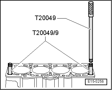
–  Carefully clean cylinder head and cylinder block sealing surfaces. Ensure no long grooves or scratches are produced (if using sandpaper, it must be at least 100 grain).
–  Carefully remove any abrasive metal particles and then the cloths.
  N15-0026
–  Position the crankshaft at TDC -arrow-.
–  Turn crankshaft back slightly.
  E13-0096
–  For centring, screw the adapters -T20049/9- in the outer front holes corresponding to the cylinder head bolts.
  E15-0256
–  Fit the cylinder head gasket with the mark facing upwards.
l  Note the dowel sleeves -arrows- on the engine block.
l  Note the fitting position of the cylinder head; the marking “oben” (up) or the part number should face the cylinder head.
The tolerance of the centring holes is narrowed at the top. Before fitting the cylinder head, check whether the adapters can be removed by pulling them upwards. If necessary, clean the edge of the adapters -T20049/9- slightly.
–  Fit the cylinder head.
–  Insert the remaining 8 bolts and tighten by hand.
–  Remove the adapters using the centre guide -T20049- into the bolt holes, screwing it to the left until the bolts can be removed.
–  Insert the two remaining cylinder head fastening bolts and also tighten by hand.
  A15-0522
–  Tighten the cylinder head bolts in tightening sequence as follows:
Continue the fitting, following the reverse order of the removal process.
  Note
On reconnecting battery, remember to enable the vehicle equipment (radio/radio navigation system, clock, electric window lifters) in line with the Instructions Manual.
Torque values
–  Tighten the cylinder head in 3 stages, in the following tightening sequence:
  V15-0738
StageTighten
I
–  Tighten using the torque wrench to 40 Nm.
II
–  Turn further with spanner 90° (1/4 turn).
III
–  Turn further with spanner 90° (1/4 turn).


Engine lubrication > < Valve stem seals: replacing