seat Workshop Repair Guides

SEAT Workshop Service and Repair Manuals

Checking valve guides > < Checking hydraulic bucket tappets
Removing and installing camshafts
(with cylinder head installed)
   
Special tools and workshop equipment required
t  Counter-hold tool -3036-
t  Chain tensioner retainer -3366-
t  Torque wrench -V.A.G 1331- (5...50 Nm)
t  Torque wrench -V.A.G 1332- (40...200 Nm)

Not illustrated
t  Sealing compound -AMV 174 004 01-
t  Sealing compound -D 454 300 A2-
Removing
–  Remove air cleaner → Rep. Gr.24
Vehicles with engine code AJH
–  Remove intake hose → Chapter, Removing and installing parts of the charge air cooling system: engine code AJH.
Vehicles with engine code AWC
–  Remove intake hose → Chapter, Removing and installing parts of the charge air cooling system: engine code AWC.
Continuation for all vehicles
–  Remove toothed belt guard upper part.
   
–  Set camshaft toothed belt pulley to TDC No. 1 cylinder by turning crankshaft. Marking on camshaft toothed belt pulley must align with mark on cylinder head cover.
–  Remove pressure hose between combination valve and secondary air pump motor from combination valve and unclip pressure hose from brackets.
  Note!
Press buttons on hose couplings to do this.
–  Remove toothed belt from camshaft pulley → Chapter.
–  Turn crankshaft back slightly.
–  Remove ignition coils with output stages → Rep. Gr.28.
–  Remove cylinder head cover.
–  Remove camshaft toothed belt pulley. When loosening camshaft toothed belt pulley bolt, hold with counterhold -3036-.
–  Remove hall sender -G40- housing.
–  Remove hall sender -G40- washer and trim.
  A15-0024
–  Clean drive chain and camshaft chain sprocket in opposite area of both arrows on bearing caps and mark installation position with a coloured mark.
  Note!
t  Do not mark chain with a centre punch or any similar means!
t  The distance between both arrows or the coloured marks is equal to 16 rollers on the drive chain.
  A15-0213
–  Secure chain tensioner with chain tensioner retainer -3366-.
  Note!
If the chain tensioner retainer is tightened excessively, this can damage the hydraulic chain tensioner.
  A15-0017
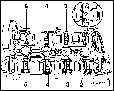
–  First remove 3rd and 5th bearing caps from inlet and exhaust camshafts.
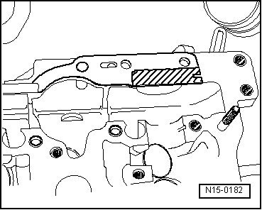
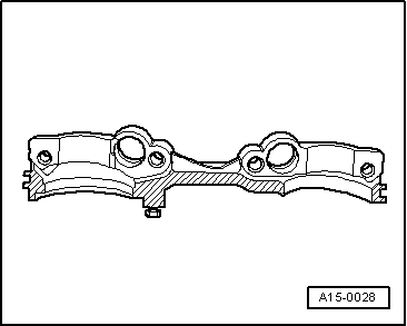
–  Remove double bearing cap.
–  Remove both bearing caps at chain sprockets on inlet and exhaust camshafts.
–  Remove chain tensioner securing bolts.
–  Remove 2nd and 4th bearing caps from inlet and exhaust camshaft alternately and diagonally.
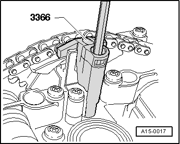
–  Remove inlet and exhaust camshaft chain tensioner and chain tensioner retainer -3366-.
Installing
  Note!
t  
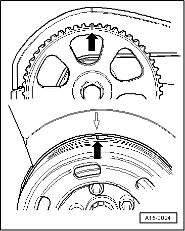
When camshafts are installed, cams for No. 1 cylinder must point upwards.
t  
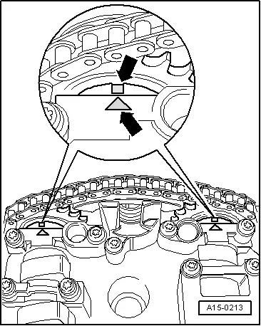
When installing the bearing caps, ensure that the cap markings can be read from the inlet side of the cylinder head.
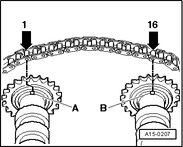
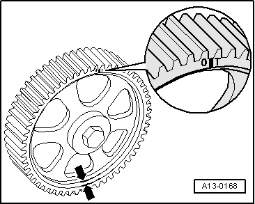
–  Fit chain onto both camshafts corresponding to coloured markings.
  Note!
  A15-0199
t  When using a new drive chain, the distance between the notches -A- and -B- on the camshafts must be 16 rollers on the drive chain.
t  The illustration shows the exact positions of the 1st and 16th rollers on the chain sprockets where the chain must be fitted.
t  Notch -A- is offset slightly towards the inside in relation to chain roller -1-.
  A15-0207
–  Renew rubber/metal gasket for chain tensioner and lightly coat hatched area with sealing compound -D 454 300 A2-.
–  Push chain tensioner in between drive chain.
–  Oil running surfaces of both camshafts.
–  Insert camshafts with drive chain and chain tensioner into cylinder head.
–  Tighten chain tensioner to 10 Nm (note fitted sleeves).
  N15-0182
–  Tighten inlet and exhaust camshaft 2nd and 4th bearing caps alternately and diagonally to 10 Nm (remember dowel sleeves).
  A15-0199
–  Install both bearing caps at inlet and exhaust camshaft chain sprockets. Check camshafts are positioned correctly -arrows- and tighten bearing cap to 10 Nm (remember dowel sleeves).
–  Remove chain tensioner retainer 3366.
  A15-0213
–  Coat double bearing cap hatched area lightly with sealing compound -AMV 174 004 01-, install and tighten to 10 Nm (note fitted sleeves).
–  Install remaining bearing caps and tighten to 10 Nm (remember dowel sleeves).
  A15-0028
–  Install camshaft sprocket (the small web faces outwards -arrow- and TDC mark is visible) and tighten securing bolt to 65 Nm (use counterhold -3036-).
  A13-0168
–  Check position of camshafts to one another -arrows- again.
–  Install washer (cone facing outwards) and tighten securing bolt to 25 Nm.
–  Install Hall sender housing and tighten to 10 Nm.
–  Install cylinder head cover.
–  Install ignition coils and tighten to 10 Nm.
Further assembly is basically the reverse of the dismantling procedure.
–  Install toothed belt and adjust valve timing → Chapter.
  Note!
When new bucket tappets have been installed the engine must not be started for about 30 minutes. Hydraulic valve compensation elements have to settle (otherwise valves will strike pistons).
  A15-0213

Checking valve guides > < Checking hydraulic bucket tappets