Leon Mk1
|

| 1 - | 20 Nm + 90° (1/4 turn) |
| q | Replace. |
| q | Respect the loosening and tightening sequence → Chapter |
| 2 - | Rocker axle |
| q | Do not mix them up |
| q | Removing and fitting → Chapter. |
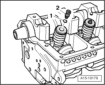
| q | Before fitting, check if all of spherical head pins and the O-rings are fitted on the injector pump units → Fig. |
| 3 - | Cylinder head bolt |
| q | Replace. |
| q | Respect the loosening and tightening sequence → Chapter |
| q | Prior to installation, insert washers → Item in cylinder head |
| 4 - | Glass |
| q | For cylinder head bolts |
| q | Insert in cylinder head before fitting bearing caps |
| 5 - | Hydraulic followers: |
| q | Do not mix them up |
| q | With hydraulic valve clearance compensation. |
| q | Set down with cam bearing surface facing downwards. |
| q | Checking axial clearance of camshaft before fitting → Chapter |
| q | Oil contact surface |
| q | Before separation, extract the half bearings from the camshaft |
| 6 - | Woodruff keys |
| 7 - | Valve plate spring |
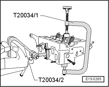
| 8 - | Exterior valve spring |
| q | Removing and fitting: with cylinder head removed → Fig. |
| q | Removing and fitting: When cylinder head is installed → Chapter |
| 9 - | Interior valve spring |
| q | Removing and fitting: When cylinder head is installed → Chapter |
| 10 - | Valve stem seal |
| q | replace when cylinder head is installed → Chapter |
| q | Replace with cylinder head removed → Fig. |
| 11 - | Valve guide |
| q | check → Chapter |
| 12 - | Injectors-pump: |
| q | Removing and installing → Chapter |
| 13 - | Cylinder head |
| q | Removing and fitting → Chapter |
| 14 - | Oil seal |
| q | Do not grease or oil the seal lip of the seal |
| q | Before fitting, use clean cloth to wipe off oil residue at camshaft journal. |
| q | To install, tape over (e.g. using Sellotape) groove in taper of camshaft |
| q | Replacement → Chapter |
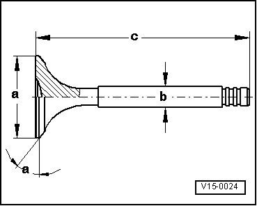
| 15 - | Valves: |
| q | Valve dimensions → Fig. |
| 16 - | Bearing shell |
| q | Do not interchange used bearing shells (mark). |
| q | Ensure that the cylinder head and the retaining lugs sit correctly on the bearing caps |
| 17 - | Camshaft: |
| q | Checking axial clearance → Chapter |
| q | Removing and fitting → Chapter |
| q | Check radial clearance with Plastigage; Wear limit: 0.11 mm |
| q | out-of-true: max. 0.01 mm |
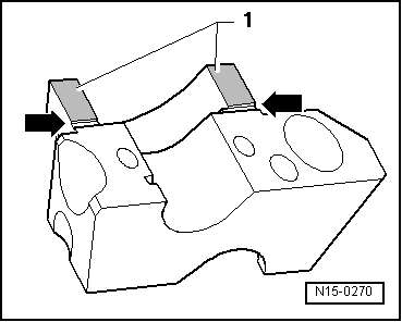
| 18 - | Bearing cover |
| q | Fitting order → Chapter |
| q | For fitting, seal the bearing cap contact surfaces 1 and 5 using AMV 174 004 01 → ETKA (Electronic parts catalogue) → Fig. |
 Caution
|
| 19 - | 8 Nm + 90° (1/4 turn) |
| q | Replace. |
 Note
Note
|
|
|
|
Note
|
|
| Dim. | Inlet valve | Outlet valve | |
| Ø a | mm | 35,95 | 31,45 |
| Ø b | mm | 6,980 | 6,956 |
| c | mm | 89,95 | 89,95 |
| α | ∠° | 45 | 45 |