
Leon Mk1
| Assembly diagram |
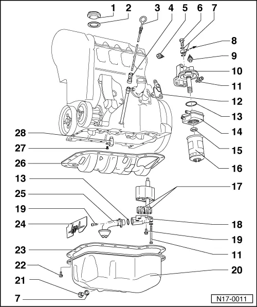
| 1 - | Cover |
| 2 - | Gasket |
| q | Replace if damaged |
| 3 - | Dipstick |
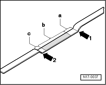
| q | Verification → Fig. |
| 4 - | Dipstick tube |
| q | Remove this for siphoning the oil |
| 5 - | Oil pressure switch -F22-, 25 Nm |
| q | 0.3 bar switch |
| q | Brown colour |
| q | Verification → Chapter |
| q | If the sealing ring is leaking, nip open and replace the o-ring |
| 6 - | Seal bolt, 25 Nm |
| q | For other engine identification letters |
| 7 - | O-ring |
| q | Replacement |
| 8 - | To the turbocompressor from the exhaust gases |
| q | For other engine identification letters |
| 9 - | Oil pressure switch -F1-, 25 Nm |
| q | 0.9 bar switch |
| q | Grey |
| q | Yellow cable |
| q | Verification → Chapter |
| q | If the sealing ring is leaking, nip open and replace the o-ring |
| 10 - | Oil filter bracket |
| 11 - | 25 Nm |
| 12 - | Gasket |
| q | Replacement |
| 13 - | O-ring |
| q | Replacement |
| 14 - | Oil cooler |
| q | To remove, first take away the oil filter → Item |
| q | Lubricate the contact surfaces with the oil filter support outside of the join ring using -AMV 188 100 02- |
| q | Ensure that there is enough space to the outer components |
| 15 - | 25 Nm |
| 16 - | Oil filter |
| q | For separation, use the oil filter spanner -U-30043- |
| q | Follow the fitting instructions printed on the filter |
| q | For fitting, tighten by hand |
| 17 - | Oil pump pinions |
| q | Removing |
| – | Remove the oil sump → Item |
| – | Remove the bolts → Item attaching the oil pump |
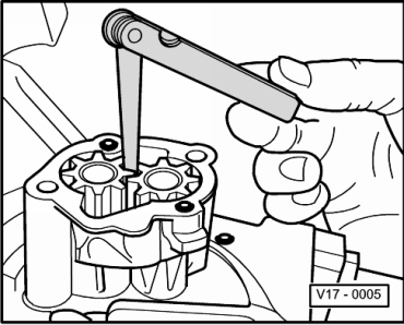
| q | Check the play between gear teeth flanks → Fig. |
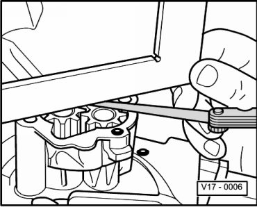
| q | Check axial play → Fig. |
| 18 - | Oil pump cover |
| q | Opening pressure: 5.7 ... 6.7 bar |
| q | Pressure regulator valve included |
| 19 - | 10 Nm |
| 20 - | Sump |
| q | Removing |
| – | Removing the sound proofing tray: → Rep. Gr.50 |
| – | Remove the lower clutch housing protection |
| – | Remove the bolts attaching the sump to the gearbox using the -U-40051A- or -U-40051+/1+/2- tool |
| – | Remove the bolts → Item |
| q | Clean sealing surface before installing |
| 21 - | Oil purge bolt, 30 Nm |
| 22 - | 20 Nm |
| 23 - | Oil sump gasket |
| q | For other engine identification letters |
| q | Replacement |
| 24 - | Baffle plate |
| q | Removing |
| – | Remove the oil sump → Item |
| – | Remove the suction pipe → Item |
| 25 - | Suction pipe |
| q | Clean filter if soiled |
| 26 - | Baffle plate |
| q | With gasket |
| q | Replace the gasket if it is deteriorated |
| 27 - | 10 Nm |
| q | Fit using -AMV 188 100 02- |
| 28 - | Oil injector |
| q | For piston cooling |
|
|
|
|