
Leon Mk1
|
 Caution
| 1 - | Seal |
| q | In cylinder head cover |
| q | Removing and installing → Chapter. |
| 2 - | Copper seal |
| q | Replace |
| 3 - | O ring |
| q | Replace |
| 4 - | Injector |
| q | If they are to be re-installed, the injectors, high-pressure pipes and clamping pieces must always be re-fitted on the same cylinder |
| q | Removing and installing → Chapter. |
| 5 - | O ring |
| q | Replace |
| 6 - | Fuel return line |
| q | To fuel tank. |
| q | With restrictor |
| q | Must not be kinked, damaged or clogged |
| q | Do not dismantle |
| q | The restrictor maintains a constant residual pressure in the fuel return lines |
| q | This residual pressure is required for the control function of the injectors |
| q | After replacement, engine must be run at idling speed for approx. 2 minutes to bleed fuel system. Then check fuel return lines for leaks |
| 7 - | Bolt. |
| q | Replace |
| q | 8 Nm + 180° |
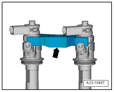
| 8 - | Clamping piece |
| q | Mark allocation for re-installation; pay attention to marking when installing |
| q | Also renew clamping piece if injector is renewed |
| q | Installation position → Fig. |
| 9 - | High-pressure line |
| q | Between fuel rail and injectors |
 Note
Note| t | The high-pressure lines may be re-used after the following checks: |
| t | Check taper seat for deformation and cracks. |
| t | The bore of the pipe must not be distorted, restricted or otherwise damaged. |
| t | Corroded lines should no longer be used. |
| q | Install free of stress |
| q | Lubricate threads of union nuts with clean engine oil |
| q | 25 Nm. |
| 10 - | Bolt. |
| q | 22 Nm. |
| 11 - | High pressure reservoir |
| q | Removing and installing → Chapter. |
| 12 - | Fuel return hose |
| 13 - | Fuel pressure regulating valve -N276- |
| q | Always renew if removed |
| q | Removing and installing → Chapter. |
| q | 80 Nm. |
| q | After renewing high-pressure pump or fuel pressure regulating valve -N276-, learnt values must be re-adapted; see „Guided Functions“ in → Vehicle diagnostic tester |
| 14 - | O ring |
| q | Replace |
| 15 - | High-pressure line |
| q | Between high-pressure pump and fuel rail |
Note| t | Note identification marks for cylinder allocation when re-installing high-pressure pipes. |
| t | The high-pressure pipes can be re-used after performing the following checks: |
| t | Check taper seat of respective high-pressure line for deformation and cracks. |
| t | The bore of the pipe must not be distorted, restricted or otherwise damaged. |
| t | Corroded lines should no longer be used. |
| q | Install free of stress |
| q | Lubricate threads of union nuts with clean engine oil |
| q | 25 Nm. |
| 16 - | Bolt. |
| q | 8 Nm. |
| 17 - | Fuel pressure sender -G247- |
| q | Removing and installing → Chapter. |
| q | 100 Nm. |
| 18 - | Grommet |
| q | In cylinder head cover |
|
|