
Leon Mk1
| Overview of fitting locations |

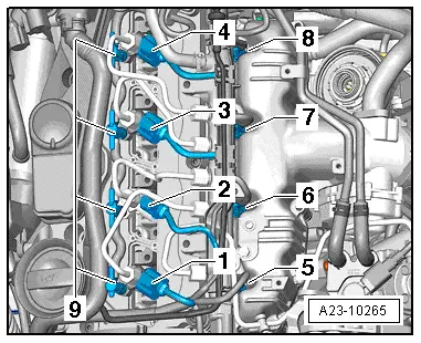
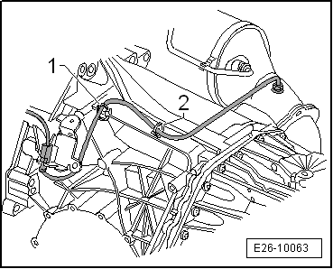
| 1 - | Air mass meter -G70- |
| q | Removing and installing → Chapter. |
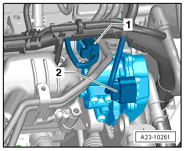
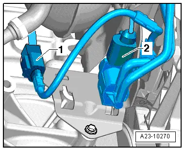
| 2 - | Electrical connectors |
| q | For Lambda probe -G39- |
| q | For exhaust gas temperature sender 3 -G495- |
| q | Installation position: |
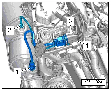
| 3 - | Lambda probe -G39- with lambda probe heater -Z19- |
| q | Fitting location → Chapter |
| q | Removing and installing → Chapter. |
| 4 - | Exhaust gas recirculation control motor -V338- with exhaust gas recirculation potentiometer -G212- |
| q | Integrated into exhaust gas recirculation cooler |
| q | Exhaust gas recirculation radiator: removing and fitting → Chapter |
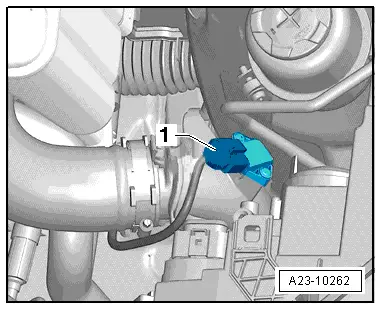
| 5 - | Exhaust gas temperature sender 3 -G495- |
| q | Fitting location → Fig. |
| q | Removing and installing → Chapter. |
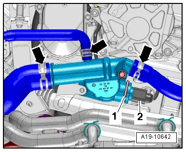
| 6 - | Radiator outlet coolant temperature sender -G83- |
| q | Fitting location → Fig. |
| q | Removing and installing → Chapter. |
| 7 - | Oil pressure switch -F1- |
| 8 - | Differential pressure sender -G505- |
| q | Fitting location → Fig. |
| q | Removing and installing → Chapter. |
| q | Adaption must be performed after renewing this component |
| 9 - | Exhaust gas temperature sender 4 -G648- |
| q | Assembly overview → Chapter |
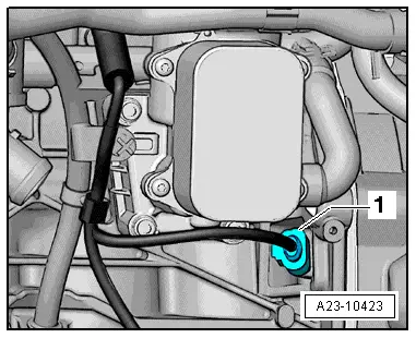
| 10 - | Coolant temperature sender -G62- |
| q | Fitting location → Fig. |
| q | Removing and installing → Chapter. |
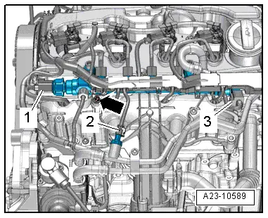
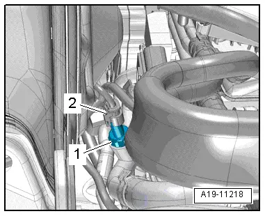
| 11 - | Fuel pressure regulating valve -N276- |
| q | Fitting location → Fig. |
| q | Removing and installing → Chapter. |
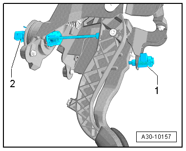
| 12 - | Accelerator position sender -G79- and accelerator position sender 2 -G185- |
| q | Fitting location → Fig. |
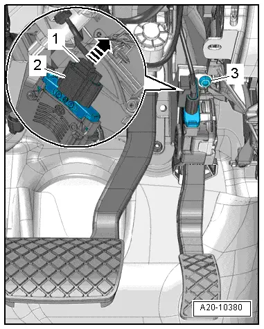
| 13 - | Brake light switch -F- and brake pedal switch -F47- |
| q | Fitting location → Fig. |
| 14 - | Clutch position sender -G476- |
| q | With clutch pedal switch for engine start -F194- and clutch pedal switch -F36- |
| q | Only on vehicles with manual gearbox |
| q | Fitting location → Fig. |
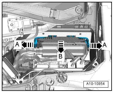
| 15 - | Engine control unit -J623- |
| q | Fitting location → Fig. |
| q | Removing and installing → Chapter. |
| 16 - | Engine speed sender -G28- |
| q | Fitting location → Fig. |
| q | Assembly overview → Chapter |
| 17 - | Pump for exhaust gas recirculation cooler -V400- |
| q | Fitting location → Fig. |
| q | Removing and installing → Chapter. |
| 18 - | Throttle valve module -J338- with throttle valve potentiometer -G69- |
| q | Fitting location → Fig. |
| q | Intake manifold: Assembly overview → Chapter |
| q | Assembly overview |
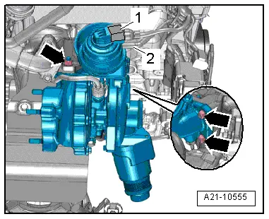
| 19 - | Supercharger pressure sender -G31- with Intake air temperature sender -G42- |
| q | Fitting location → Fig. |
| q | Removing and installing → Chapter. |
| 20 - | Fuel temperature sensor -G81- |
| q | Fitting location → Fig. |
| 21 - | Fuel metering valve -N290- |
| q | Fitting location → Fig. |
| q | Removing and installing → Chapter. |
| 22 - | Glow plugs |
| q | Glow plug 1 -Q10- |
| q | Glow plug 2 -Q11- |
| q | Glow plug 3 -Q12- |
| q | Glow plug 4 -Q13- |
| q | Fitting location → Fig. |
| q | Removing and installing → Chapter. |
| q | Assembly overview → Chapter |
| 23 - | Fuel pressure sender -G247- |
| q | Fitting location → Fig. |
| q | Removing and installing → Chapter. |
| 24 - | Hall sender -G40- |
| q | Fitting location → Fig. |
| q | Removing and installing → Chapter. |
| q | Assembly overview → Chapter |
| 25 - | Injectors |
| q | Fitting location → Fig. |
| q | Removing and installing → Chapter. |
| 26 - | Charge pressure control solenoid valve -N75- |
| q | Fitting location → Fig. |
| 27 - | Exhaust gas recirculation cooler changeover valve -N345- |
| q | Fitting location → Fig. |
| 28 - | Position sender for charge pressure positioner -G581- |
| q | Fitting location → Fig. |
|
|
|
 Note
Note
|
|
|
|
|
|
|
|
|
|
|
|
|
|
|
|
|
|
|
|
|
|
|
|
|
|
|
|
|
|
|
|
|
|
|
|
|
|