| t
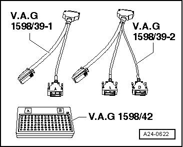
| The smaller of the two connectors in the engine control unit has terminals 1 to 60. The larger of the two connectors has terminals 1 to 94. |
| t
| The test box -V.A.G 1598/42- is designed so it can be connected both to the wiring harness for the engine control unit and to the engine control unit itself at the same time. |
| t
| This has the advantage that, when the test box is connected, the electronic engine control remains totally operative (for example, measurement of signals with the engine running). |
| t
| If the engine control unit should also be connected to the test box, this is indicated in the corresponding test cycles. |

WARNING | To prevent irreparable damage to the electronic components, select appropriate measuring range before connecting the measuring cables and observe the test requirements. |
|
| –
| Connect the test box -V.A.G 1598/42- using the adapter cable -V.A.G 1598/39-1- or the adapter cable -V.A.G 1598/39-2- to the wiring harness. Connect earth clip of test box to negative terminal of battery. The instructions for performing the individual tests indicate whether or not the engine control unit itself also needs to be connected to the test box. |
| –
| Carry out the test, as described in the relevant repair procedures. |
| Installing engine control unit |
| The assembly takes place in the reverse series; the protective housing is again attached on the engine control panel. New shear bolts must be used. |
| Carry out the following jobs after re-connection of the engine control panel: |
| –
| Interrogate and, if necessary, erase fault memory. |
|
|
|
 Note
Note