Leon Mk1
| Bodywork cooling system components: |
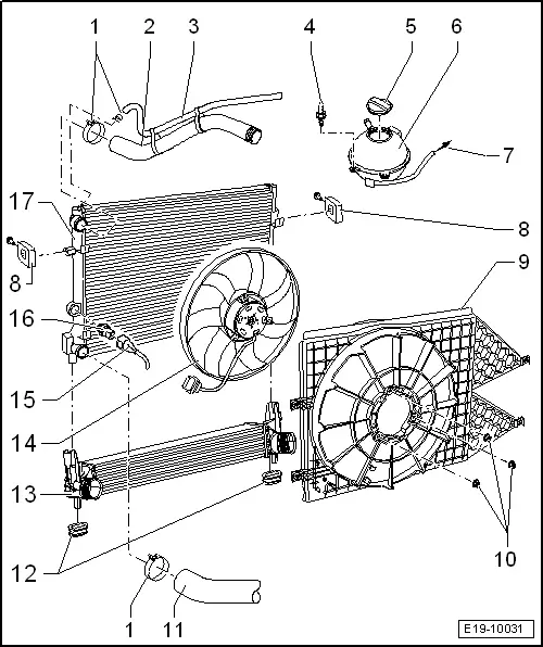
| 1 - | Spring-type hose clip |
| 2 - | Upper coolant hose |
| q | Note fitting position: |
| q | Coolant hose schematic diagram → Chapter |
| 3 - | Coolant hose |
| 4 - | 10 Nm |
| 5 - | Sealing plug |
| 6 - | Expansion tank |
| q | Perform cooling system leakage check with Cooling system tester -SAT 1274- and the Adaptor -VAG 1274/8- |
| 7 - | To coolant metal pipe |
| q | Coolant hose schematic diagram → Chapter |
| 8 - | Upper support |
| q | 10 Nm fastening bolts |
| q | Note fitting position: |
| q | Note that there are various versions |
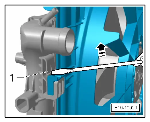
| 9 - | Cowling |
| q | Remove the air duct from the coolant radiator → Fig. |
| 10 - | 10 Nm |
| 11 - | Lower coolant hose |
| q | Note fitting position: |
| q | Coolant hose schematic diagram → Chapter |
| 12 - | Lower mounting |
| 13 - | Charge air cooler |
| q | removing and fitting → Chapter |
| q | Attached to radiator at upper part |
| 14 - | Electric ventilator |
| 15 - | Connector |
| 16 - | Radiator fan thermoswitch -F18-, 35 Nm |
| q | For the electric ventilator |
| Switching temperatures |
| – | 1st gear: Turn on: 92 ... 97 ℃, Turn off: 84 ... 91 ℃ |
| – | 2nd gear: Turn on: 99 ... 105 ℃, Turn off: 91 ... 98 ℃ |
| 17 - | Radiator |
| q | removing and fitting → Chapter |
| q | Renew coolant after replacing |
| q | Attached to intercooler at lower part |