seat Workshop Repair Guides

SEAT Workshop Service and Repair Manuals

Exhaust system > < Engine control unit
Intake manifold: removing and installing
t  Removing → Anchor
t  Installing → Anchor
Consult the equivalence table for tools and equipment according to applicability among Seat / VW / Audi / Skoda → Chapter.
Special tools and workshop equipment required
   
t  Torque wrench kit -SAT 8010-, see equivalent → Anchor
  L00-10226
t  Pliers -T20174- or pliers -SAT 1105-, see equivalent → Anchor
  W00-2456
Special tools and equipment for engines with particulate filter
t  Socket wrench e/c 22 -T20202A-, see equivalent → Anchor
t  Socket wrench e/c 17 -T20211-, see equivalent → Anchor
t  Articulated wrench e/c 17 -T20212-, see equivalent → Anchor
t  Ratchet 1/2' x 9-12 -VAG 1331/1-, see equivalent → Anchor

Removing
   
–  Release the fasteners -arrows- to remove the central soundproofing panel.
  E10-0086
–  Unscrew the bolts -arrows- and remove the heat protecting plate.
–  Remove right-hand articulated shaft: → Running gear, shafts, steering; Rep. gr.40.
Only for engines with particulate filter
  A10-0921
–  Unbolt the pressure pipe -2- using the articulated wrench E/C 17 -T20212-.
–  Unbolt the temperature sender after the particulate filter -G527--1- using the articulated wrench E/C 17 -T20212-.
Continue for all engines
  E26-10042
–  Detach the outer -1- and inner -2- engine covers, by pulling them evenly upwards.
  E01-10018
–  Separate the clamps -arrows- and remove the supercharger hose -1-.
  E21-10034
–  Detach electrical connector -1- of the engine intake manifold flap -V157-.
–  Unscrew the bolts -arrows- and remove the intake manifold flap motor -V157-.
  Note
For improved understanding, it is shown from the rear in the illustration with engine removed.
  A10-10029
–  Disconnect the electrical connector -1- on the exhaust gas recirculation valve -N18- with the potentiometer for regulating exhaust gases -G212-.
–  Remove the electrical harness from the brackets and move to one side.
–  Remove bolts -arrows-.
–  Remove the exhaust gas recirculation valve -N18- of the intake manifold.
Only for engines with particulate filter
  A10-10030
–  Disconnect the connectors -1-, -2-, -3- and -4- and remove them from their housings.
  E26-10032
–  Undo the pressure pipe -3- of the particulate filter using the socket wrench E/C 17 -T20211-.
–  Undo the lambda probe -G39--1- using the socket wrench E/C 22 -T20202A- and the "ratchet 1/2" x 9-12" -VAG 1331/1-.
–  Unscrew the bolts -arrows- and free heatproof plate of the particulate filter -4- without removing it.
  E21-10027
–  Undo the exhaust gas temperature sender 2, bench 1 -G448--2- using the socket wrench E/C 17 -T20211- and the "ratchet 1/2" x 9-12" -VAG 1331/1-.
  E26-10041
–  Disconnect the electrical connector -arrow- for temperature sender 1 of the exhaust gases -G450-.
–  Unscrew exhaust gas pressure sensor 1 -G450- and remove together with the pressure hoses.
–  Remove the heatproof plate of the particulate filter.
–  Unscrew the brackets of the particulate filter → Item.
  A26-10188
–  Remove the bolts -arrows- and remove the upper support of the particulate filter.
Only for engines without particulate filter
–  Remove the bracket for front exhaust pipe → Item.
Continue for all engines
  E26-10034
–  Unscrew the nuts on the double clamp -1-.
  Note
The flexible pipe connection (de-coupling element) in the front exhaust pipe must not be bent more than 10° - otherwise it can be damaged.
  A26-0734
–  Remove the support bolts of the particle filter and the engine block, and remove the support.
–  Remove the front exhaust pipe with the particulate filter / catalytic converter and place it on the power steering.
–  Separate the low pressure hoses if necessary.
  A26-10190
–  Remove the bolts -arrows- which are in the flange found between the exhaust gas recirculation radiator and the intake manifold.
  A23-10004
–  Remove the air filter intake hose -3-.
–  Detach connection hose -2-.
  E26-10033
–  Unscrew the nuts -arrows- and take connecting pipe for exhaust gas recirculation off.
  A26-10191
–  Remove the bolts -1-, -2- and the hollow bolt -3- and remove the oil return pipe.
  A21-10088
–  Remove the thermal protection plate on the left of the exhaust manifold -arrows-.
–  Remove air filter → Chapter.
  A26-10201
–  Undo the fastening bolts of the turbocharger and of the bracket -arrows-.
  A21-0306
–  Remove nuts -arrows-.
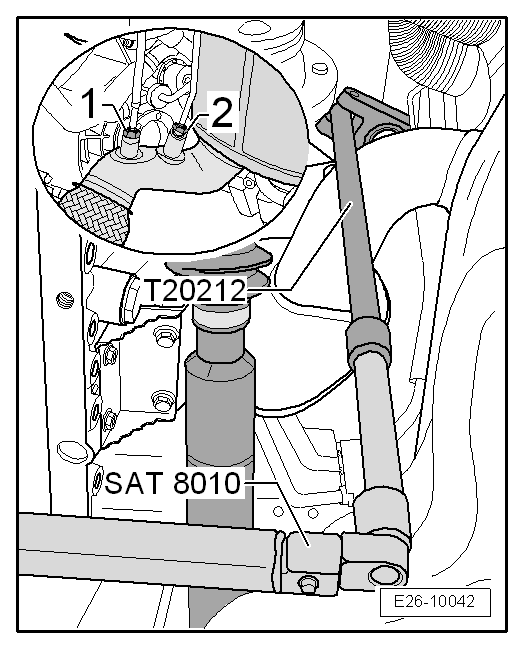
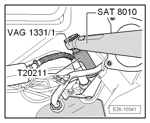
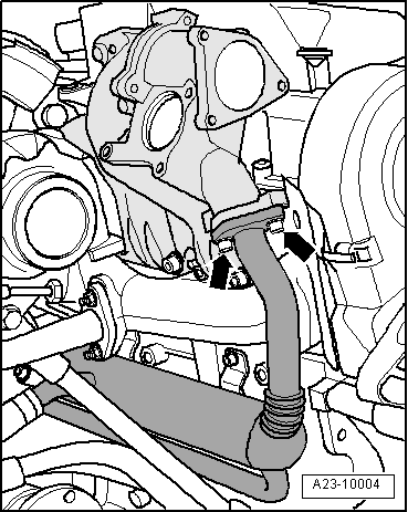
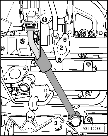
–  Remove the exhaust manifold assembly/turbocharger and place it on the power steering.
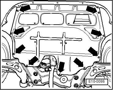
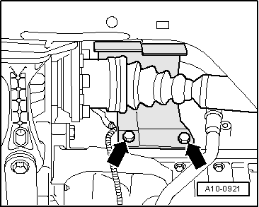
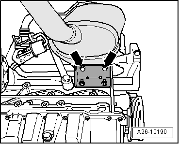
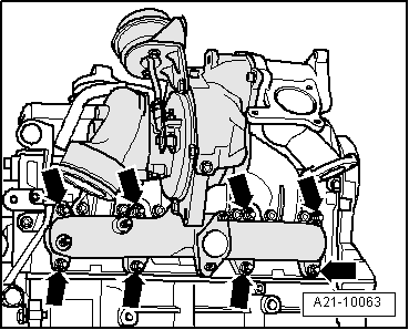
–  Remove the six bolts which secure the intake manifold to the cylinder head and remove it from the top.
Installing
Install in the reverse order from removal, remembering the following:
  Note
t  
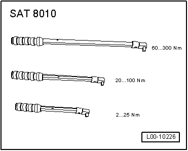
Apply the correct tightening torques.
t  Renew seals, gaskets and self-locking nuts.
t  Note the installation position of intake manifold gasket.
t  
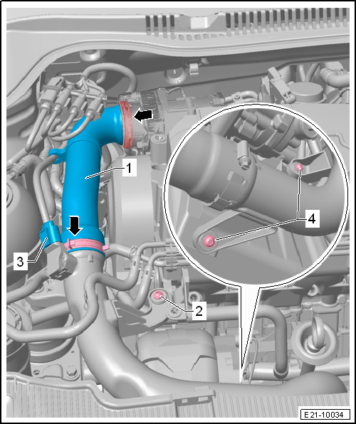
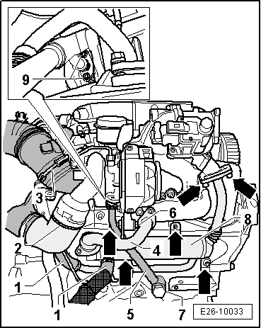
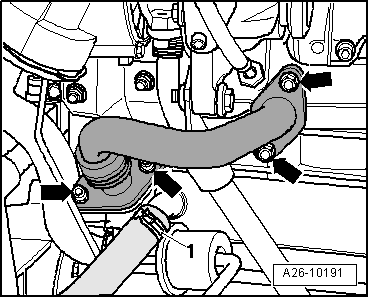
The sleeves for the hoses and the supercharger air flow tubes should be free of oil and grease before fitting.
t  
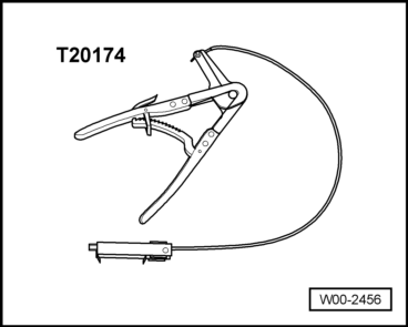
Secure all hose connections with the correct hose clips (same as original equipment) → Parts catalogue.
  A21-10063

Exhaust system > < Engine control unit