seat Workshop Repair Guides

SEAT Workshop Service and Repair Manuals

Removing and installing coolant pipe (front) > < Removing and installing 4/2-way valve with thermostat
Coolant: emptying and filling
t  Coolant: Draining → Anchor
t  Coolant: filling → Anchor.
t  Fill coolant system using cooling system charge unit -VAS 6096- → Anchor
t  Fill coolant system without using cooling system charge unit -VAS 6096- → Anchor
Consult the equivalence table for tools and equipment according to applicability among Seat / VW / Audi / Skoda → Chapter.
   
Special tools and workshop equipment required
t  Refractometer -T10007-, see equivalent → Anchor
t  Adapter for cooling system tester -V.A.G 1274/8-, see equivalent → Anchor
t  Coolant tester -VAS 6096-, see equivalent → Anchor
t  Collector tray for workshop crane -VAS 6208-, see equivalent → Anchor
t  Base -VAS 6499-, see equivalent → Anchor

t  Base -VAS 6340-, see equivalent → Anchor
Empty
  Note
Collect drained coolant in a clean container for re-use or disposal.
  WARNING
Hot vapour/hot coolant may escape when opening expansion tank. Cover cap with cloth and open carefully.
–  Open cap on coolant expansion tank.
   
–  Fit the centre noise insulation -fasteners 1 ... 3-.
  A10-1565
–  Remove air hose; loosen hose clip -2- and raise retaining clip -1- for this.
  WARNING
Cover the intercooler opening, for example, using a clean cloth made of spongy material so that coolant does not enter.
–  Place the drip tray -VAS 6208- under the engine.
  A21-10336
–  Pull coolant hoses -1- off coolant circulation pump 2 -V178--2-.
  N19-10263
–  Pull off lower coolant hose retaining clip -arrow- and remove coolant hose from quick-release connection of radiator.
  A19-0482
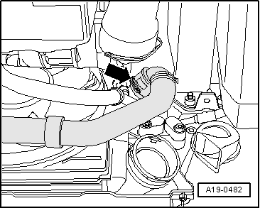
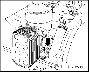
–  To drain coolant from engine also remove coolant hose from oil cooler -arrow-.
  Note
Please observe requirements for disposal.
Filling
  Note
The amount of water used in the coolant mixture has a great influence on its effectiveness. With respect to the contents that may vary from country to country, or even region to region, Volkswagen has made the decision to define the quality of the water that is used for the cooling system. Distilled water fulfils all requirements. It is therefore recommended that distilled water be mixed with the coolant whenever an older model's coolant is replenished or replaced. The use of purified water is mandatory for the newest models (year of manufacture 2010 ►).
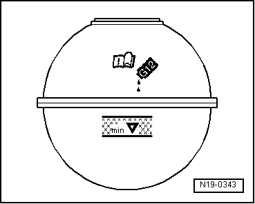
  Caution
Only distilled water may be mixed with G12 plus-plus. The use of distilled water ensures optimum protection against corrosion.
  Note
t  Only use antifreeze additive G 12 plus-plus according to specification TL VW 774 G.
t  It is only permissible to use distilled water for mixing.
t  „TLºVWº774ºG“ or „TLºVWº774ºF“ anti-freeze agents prevent damage from rust, freezing or lime sediment, and also raise the boiling point of the coolant. For these reasons, the cooling system must be filled all year round with an anti-freeze and anti-corrosion agent.
t  In countries with a tropical climate, the cooling liquid increases the boiling point and guarantees secure operation when the engine is put under strain.
t  Frost protection must be assured to about -25 °C (in arctic climatic countries to about -35 ℃).
t  During hotter seasons of the year and in hot countries, the coolant concentration should not be reduced by adding only water. The amount of anti-freeze in the coolant must be at least 40 %.
t  If for climatic reasons it is necessary to increase the coolant protection, you may raise the proportion of the antifreeze agent and anti-corrosive, but without exceeding 60% (antifreeze protection up to -40 ºC), from this proportion the antifreeze protection is diminished, aside from reducing the coolant capacity.
t  If radiator, heat exchanger, cylinder head or cylinder head gasket has been replaced, do not reuse old coolant.
t  
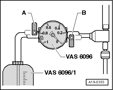
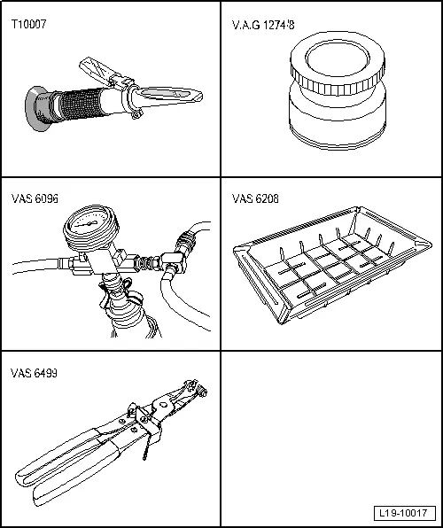
For checking anti-freeze protection in cooling system, use refractometer -T10007-.
t  Secure all hose connections with the correct type of hose clips (same as original equipment) → Parts catalogue.
Recommended mixture ratios:
  N19-10286
Anti-freeze protection
up to
Anti-freeze
proportion
G 12 plus-plus 1)Purified Water 1)
-25 ℃
-35 ℃
-40 ℃
40 %
50 %
60 %
3.2 l
4.0 l
4.8 l
4.8 l
4.0 l
3.2 l
l  1)Coolant quantity may differ depending on vehicle equipment

   
–  Fit the lower coolant hose to the radiator-arrow-.
–  Connect coolant hoses to oil cooler and coolant circulation pump 2 -V178-.
  A19-0482
–  Fix hose clip -2- and lift retaining clip -1- to install the air hose.
  A21-10336
–  Fit the centre noise insulation -fastening parts 1 ... 3-.
  A10-1565
Fill coolant system using the cooling system charge unit -VAS 6096-:
–  Fill coolant reservoir -VAS 6096/1- with at least 8 l premixed coolant of the right mixture ratio:
l  »G12+« (40 %) and water (60 %), for a protection to -25 ℃
l  »G12+« (50 %) and water (50 %), for a protection to -35 ℃
l  »G12+« (60 %) and water (40 %), for a protection to -40 ℃
–  Fit adaptor for cooling system tester -V.A.G 1274/8- to the coolant expansion tank.
–  Fit charger -VAS 6096- onto adaptor -V.A.G 1274/8-.
–  Run vent hose -1- into a small container -2-. When flashing off a small quantity of coolant is carried away, which is to be collected.
–  Connect both valves -A- and -B- (lever arm transverse to direction of flow).
–  Connect hose -3- to compressed air.
l  Pressure: 6…10 bar
  A19-0351
–  Open valve -B- (lever arm pointing in direction of flow).
The suction jet pump creates a vacuum in the cooling system.
l  The display instrument needle must move to the green area.
–  Also briefly open valve -A- (turn lever in direction of flow) so that the charger -VAS 6096- hose can fill with coolant.
–  Close valve -A- again.
–  Leave valve -B- open for another 2 minutes.
l  The suction jet pump creates further vacuum in the cooling system.
l  The pointer of the indicator must remain in the green zone.
–  Close valve -B-.
l  The display instrument needle must remain in the green area so that the vacuum in the cooling system is sufficient to continue with the refilling.
If the needle does not reach the green zone, repeat the process.
If the vacuum drops the cooling system is leaking.
–  Pull out pressure hose.
–  Open valve -A-.
The vacuum in the cooling system causes the coolant to be drawn out of the cooling system charge unit -VAS 6096/1-; the cooling system is then filled.
  A19-0353
–  Check coolant level and fill coolant up to max. mark.
–  Start engine and run at approx. 1500rpm for max. 2 minutes and at the same time fill with coolant up to overflow hole on expansion tank.
–  Screw on cap on coolant expansion tank.
–  Run engine until radiator fan cuts-in.
  WARNING
Hot vapour/hot coolant may escape when opening expansion tank. Cover cap with cloth and open carefully.
–  Check coolant level and top-up if necessary.
l  When the engine is at normal operating temperature, the coolant level must be on the max. mark and between the min. and max. marks when the engine is cold.
–  Switch off the engine.
  A19-0480
Fill coolant system without using cooling system charge unit -VAS 6096-:
–  Slowly fill coolant to upper marking of shaded field on expansion tank.
–  Close expansion tank.
–  Start the engine and keep the engine speed at approx. 2000 / min for approx. 3 minutes.
–  Then run engine at idling speed until radiator fan cuts in.
–  Check coolant level and top up any missing coolant, if necessary. When the engine is at normal operating temperature, the coolant level must be at the top mark, and when the engine is cold, in the middle of the shaded area.
  N19-0343

Removing and installing coolant pipe (front) > < Removing and installing 4/2-way valve with thermostat