seat Workshop Repair Guides

SEAT Workshop Service and Repair Manuals

Removing and installing upper front coolant pipe > < Coolant: emptying and filling
Removing and installing coolant pipe (front)
t  Coolant pipe - front: Removing → Anchor
t  Coolant pipe - front: Fitting → Anchor
Consult the equivalence table for tools and equipment according to applicability among Seat / VW / Audi / Skoda → Chapter.
   
Special tools and workshop equipment required
t  Release lever -80 - 200-, see equivalent → Anchor
t  Hose clamps up to Ø 25 mm -3094-, see equivalent → Anchor
t  Collector tray for workshop crane -VAS 6208-, see equivalent → Anchor
t  Base -VAS 6499-, see equivalent → Anchor

Removing
–  Place drip tray for workshop cranes -VAS 6208- beneath engine.
–  Drain coolant → Chapter.
   
–  Remove the engine cover upwards -arrows-.
–  Remove the air filter housing → Chapter.
  E10-10085
–  Remove battery → Electrical system; Rep. gr.27
  A27-0193
–  Unscrew bolts -arrows- and remove battery mounting bracket -1-.
–  Disconnect the crankcase breather hose -1- for the cylinder head cover. To do so, press the tabs.
  A27-10166
–  Free vacuum hoses -arrows- at air pipe.
–  Unscrew bolt -2-, swing air pipe with inlet connection to rear and pull from turbocharger.
  A21-10487
–  Unclip wiring harness from bracket -arrow-.
  N15-10410
Vehicles with dual clutch gearbox:
–  Disconnect the coolant hoses using the hose clip -3094- and remove from the gearbox oil cooler. Unfasten hose clamps -arrows- for this purpose.
  A10-10001
All vehicles (continued):
–  Free wiring harnesses -arrows- and electrical connector -1- at bracket.
  A10-11009
–  Remove air hose. Release hose clips -1- and -2- for this.
  A21-10488
–  Unscrew bolts -2, 5- and -arrows-.
–  Free electrical lines and hoses on left air pipe using removal lever -80 - 200-.
–  Release hose clip -3- and remove left air pipe.
  Note
Ignore positions -1- and -4-.
  A21-10493
–  Loosen the hose clips -1- using the hose spring-type clip pliers -VAS 6499- and remove the coolant hoses.
  Note
Disregard items -2-, -3- and -4-.
  A19-10992
–  Remove electrical connector -1- for Hall sender -G40- from bracket.
–  Remove bracket from front from coolant pipe.
  A19-10993
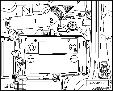
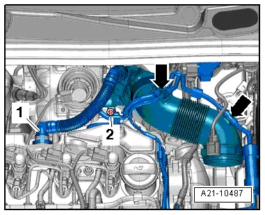
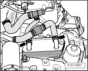
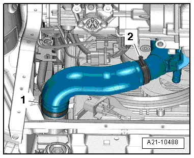
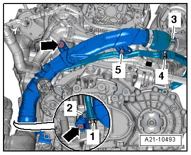
–  Release hose clips -2- and -3-, and pull coolant hoses off.
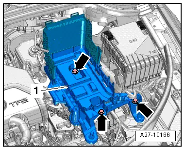
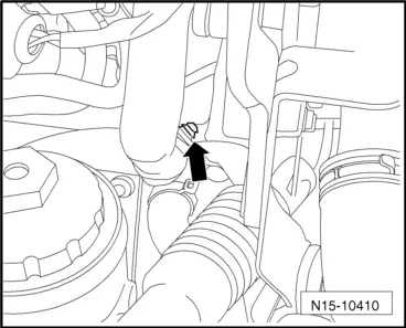
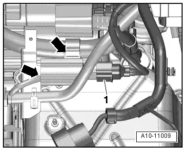
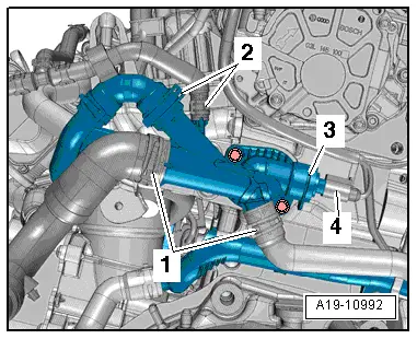
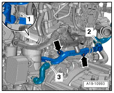
–  Unscrew bolts -arrows- and pull front coolant pipe out of 4/2-way valve.
Installing
l  Tightening torques → Chapter
Installation is carried out in reverse sequence; note the following:
  Note
t  Renew gaskets, seals and O-rings.
t  Hose connections and air pipes and hoses must be free from oil and grease before fitting.
t  Secure all hose connections with the correct type of hose clips (same as original equipment) → Electronic parts catalogue.
–  Clean or smoothen sealing surface for O-ring.
–  Moisten O-ring with coolant and slide onto front coolant pipe.
–  Push front coolant pipe into 4/2-way valve.
–  Electrical connections and routing → Current flow diagrams, Electrical fault finding and Fitting locations.
–  Fill coolant system with coolant → Chapter.
  A19-10993

Removing and installing upper front coolant pipe > < Coolant: emptying and filling