seat Workshop Repair Guides

SEAT Workshop Service and Repair Manuals

Coolant: emptying and filling > < Coolant circulation pumpV178: Removing and installing
Removing and installing 4/2-way valve with thermostat
t  4/2-way valve with thermostat: Removing → Anchor
t  4/2-way valve with thermostat: Fitting → Anchor
Consult the equivalence table for tools and equipment according to applicability among Seat / VW / Audi / Skoda → Chapter.
   
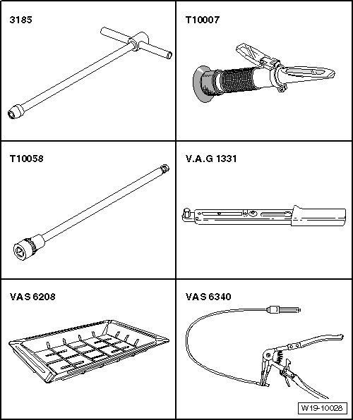
Special tools and workshop equipment required
t  Articulated wrench e/c 10 -VAS 3185-, see equivalent → Anchor
t  Refractometer -T10007-, see equivalent → Anchor
t  Spanner -T10058-, see equivalent → Anchor
t  Torque wrench (5 - 50 Nm) -V.A.G 1331-, see equivalent → Anchor
t  Collector tray for workshop crane -VAS 6208-, see equivalent → Anchor
t  Base -VAS 6340-, see equivalent → Anchor

  Note
The thermostat is located within the 4/2-way valve and cannot be replaced individually.
Removing
–  Drain coolant → Chapter.
   
–  Remove the engine cover upwards -arrows-.
  E10-10085
–  Unplug connector -1- from air mass meter -G70-.
–  Separate the hose -3-.
–  Remove the air intake hose, and release the hose clip -2-.
–  Unscrew the bolt -4- and remove the air filter housing.
  WARNING
Observe safety precautions when disconnecting the battery → Electrical system; Rep. gr.27.
–  With the ignition switched off, disconnect the battery earth lead → Electrical system; Rep. gr.27.
–  Remove battery and battery tray → Electrical system; Rep. gr.27.
  A23-10314
–  Remove the hose for the crankcase ventilation -1- from the cylinder head cover. To do so, press the tabs.
–  Free vacuum hoses -arrows- at air pipe.
  A21-10487
–  Unscrew bolt -2-, swing air pipe with inlet connection to rear and pull from turbocharger.
  A21-10487
–  Unclip wiring harness from retainer -arrow-.
  N15-10410
–  Move the wiring harnesses -arrows- and electrical connector -1- clear at bracket.
  A10-11009
–  Unscrew bolts -2-, -5- and -arrows-.
–  Use removal lever -80 - 200- to move cable guides and hoses at air pipe (left-side) clear.
–  Release the hose clamp -3- and remove the left charge air pipe.
  Note
Ignore positions -1- and -4-.
  A21-10493
–  Disconnect the coolant hoses by releasing the hose clamps -1-.
  Note
Disregard items -2-, -3- and -4-.
  A19-10992
–  Remove the electric connector -1- of the Hall sender -G40- from its bracket.
–  Undo the screws -arrows-; remove the front coolant pipe on the 4/2-way valve to the left and leave in the installation position.
  Note
Ignore positions -2- and -3-.
  A19-10993
–  Pull coolant pipe out of connection -C- for 4/2-way valve. Leave in its installation position.
  N19-10386
–  Remove bolts -arrows-.
–  Free coolant hose -3-.
–  Release the hose clamp -2-.
–  Unplug electrical connector -1- at charge air pressure sender -G31-/charge air pressure sender -G42- and remove the right air intake pipe.
–  Remove the alternator → Electrical system; Rep. gr.27.
  A21-10435
–  Pull out the dipstick a little and unscrew the bolt -1-.
–  Hang out the clip -2- using the lever -80 200-.
–  Pull oil dipstick guide tube off cylinder block upwards and push to side.
  A17-10509
–  Pull coolant hoses off connections -A, B and D-.
–  Remove securing bolts -3- for 4/2-way valve -2-.
–  Remove the 4/2-way valve with thermostat.
Installing
l  Tightening torque → Chapter
Reassembly is carried out in the reverse order; note the following:
–  Install the guide tube for the dip stick.
–  Install the front coolant pipe.
–  Install the alternator → Electrical system; Rep. gr.27.
–  Install the air hoses
–  Install intake pipe.
–  Electrical connections and routing → Current flow diagrams, Electrical fault finding and Fitting locations.
–  Install the battery socket and battery → Electrical system; Rep. gr.27.
–  Install the air filter housing.
–  Install air hoses with screw clamps → Chapter
–  Fill up with coolant → Chapter.
  N19-10386

Coolant: emptying and filling > < Coolant circulation pumpV178: Removing and installing