
Leon Mk1
| Renewing valve stem seals with cylinder head removed |
| Special tools and workshop equipment required |
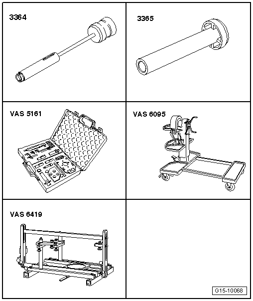
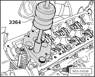
| t | Valve stem seal puller -3364- |
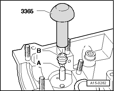
| t | Valve stem seal fitting tool -3365- |
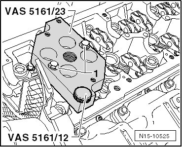
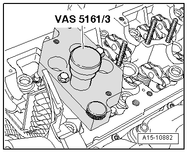
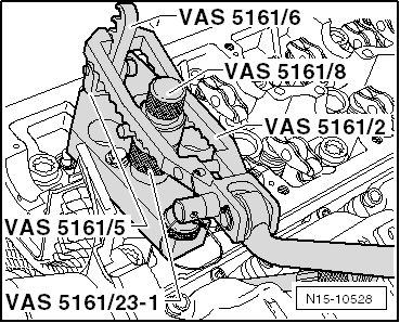
| t | Removal and installation device for valve cotters -VAS 5161- with guide plate -VAS 5161/23- and sleeve -VAS 5161/23-1- |
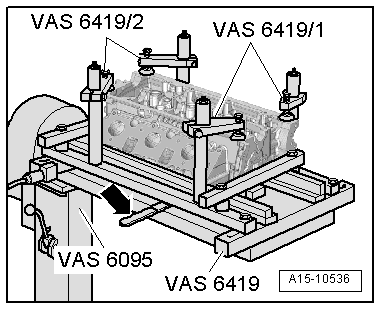
| t | Engine and gearbox support -VAS 6095- |
| t | Cylinder head tensioning device -VAS 6419- |
| t | 2x M6x30 bolts |
|
|
|
|
|
|
|
|
|
|
|
|
|
 Caution
|
|
|
|