seat Workshop Repair Guides

SEAT Workshop Service and Repair Manuals

Engine cooling > < Cooling system components
Installing a new balancer shaft module
Special tools and workshop equipment required
   
t  Locking tool -T10255-
Procedure
l  Specified torques → Chapter „Assembly overview - oil pump, sump, balancer shaft module“.
l  
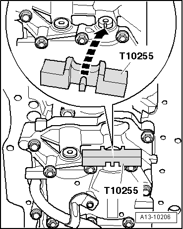
Crankshaft locked in position with crankshaft stop -T10050-.
  Note
t  
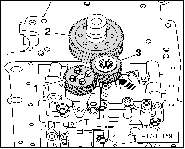
The drive spur of the balancer shaft module must with a tooth backlash of 0.038 ... 0.072 mm.
t  
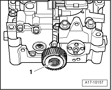
A coating of correct thickness is applied to the new intermediate gear wheel to set the correct backlash. The coating is applied in part around the teeth.
t  The coating is quickly worn away, which sets the correct backlash.
t  A new balancer shaft module must always be installed with a new intermediate gear wheel with coating.
t  
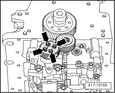
Renew bolts tightened through an additional specified angle.
  Caution
Risk of thrust washer slipping behind intermediate gear wheel.
To fit balancer shaft module, do not loosen intermediate gear wheel bolt more than specified. Thrust washer installation position → Fig.
  W00-10250
–  Loosen bolt -1- for intermediate gear wheel approx. 45°.
–  Insert dowel sleeves if no dowel sleeves for centring balancer shaft module are fitted on cylinder block.
–  Place balancer shaft module on cylinder block.
l  Coating on intermediate gear wheel must not be damaged.
–  Tighten bolts for balancer shaft module:
   Balancer shaft module with 8 threaded connection points → Fig.
   Balancer shaft module with 6 threaded connection points → Fig.
  A17-10157
–  Lock balancer shaft with locking tool -T10255-; if necessary, turn balancer shaft.
l  Locking tool pin must engage in groove in balancer shaft when doing this.
  A13-10206
–  Carefully fit balancer shaft gear wheel onto balancer shaft; push intermediate gear wheel slightly to side for this.
l  Coating on intermediate gear wheel must not be damaged.
l  If possible, threaded holes of balancer shaft should be located centrally in elongated holes of balancer shaft gear wheel.
  Note
If elongated holes in balancer shaft gear wheel cannot be aligned to threaded holes, balancer shaft gear wheel must be turned by respective number of teeth and fitted again.
–  Tighten bolts -arrows- for balancer shaft gear wheel.
–  Remove locking tool -T10255-.
  Note
  A17-10160
The following 3 procedures must be performed simultaneously (2nd mechanic required).
–  Press the intermediate wheel -3- with force in the -direction of the arrow- until the splines of the spur gear -2- and the balance shaft pinions -1- engage. If necessary, use a wooden bar as an aid.
–  Turn balancer shaft gear wheel slightly anticlockwise whilst doing this.
–  Tighten bolt for intermediate gear wheel.
–  Remove crankshaft stop -T10050-.
  Note
No backlash may be perceptible after installing intermediate gear wheel. This can be checked by hand using light force.
Remaining installation steps are carried out in reverse sequence; note the following:
–  Install sump → Chapter.
–  Install vibration damper → Chapter.
  A17-10159

Engine cooling > < Cooling system components