seat Workshop Repair Guides

SEAT Workshop Service and Repair Manuals

cylinder block: Assembly overview > < Belt routing: Assembly overview
Removing and installing engine bracket
t  Engine mounting: Removing → Anchor.
t  Engine support: assembly → Anchor
Consult the equivalence table for tools and equipment according to applicability among Seat / VW / Audi / Skoda → Chapter.
Special tools and workshop equipment required
   
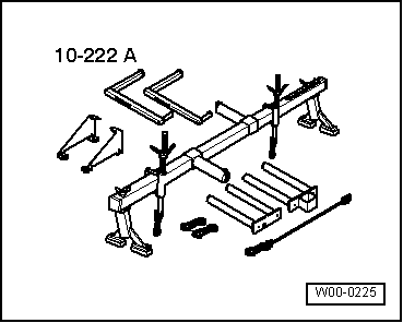
t  Suspension tool -10 - 222 A-, see equivalent → Anchor
  W00-0225
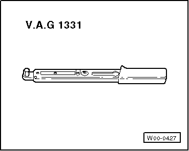
t  Torque wrench (5 - 50 Nm) -V.A.G 1331-, see equivalent → Anchor
  W00-0427
Removing
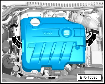
–  Remove the engine cover upwards -arrows-.
  E10-10085
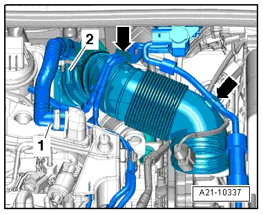
–  Disconnect the hoses -1- on the vent on the crankshaft case. Press in to release the retaining clips.
–  Move clear vacuum hoses -arrows- at air pipe.
–  Release hose clip -2- and detach air pipe.
–  Turn back the flexible air conduction tube and detach it from the exhaust gas turbo compressor.
–  Remove the supplementary fuel pump -V393- → Chapter.
  A21-10337
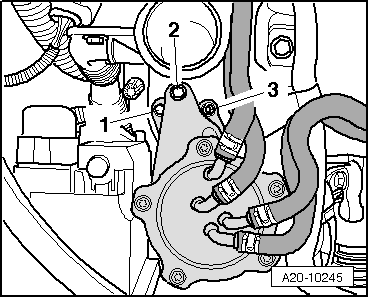
–  Loosen the bolt by one turn -1-.
–  Remove bolt -2- and nut -3-.
–  Leave the fuel filter to one side with the flexible hoses.
  A20-10245
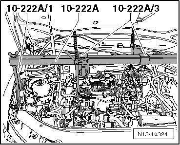
–  Fit the support tool -10 - 222 A- with the necessary adapters and attach as shown in the figure.
  Note
t  When removing the bearing, the engine must be secured using the support bracket -10 222A-.
t  The engine mount may only be loosened once the powertrain support assembly has been fitted.
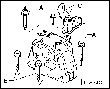
–  Unscrew bolts -B- and -C-.
  N13-10324
–  Undo the bolts -A- and remove the engine mount.
  N10-10280
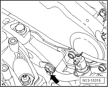
–  Unscrew the fixing screw of the coolant pipe -arrows-.
–  Remove the front right wheel housing moulding.
  N13-10316
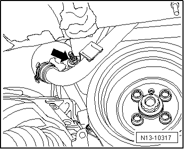
–  Remove securing bolt of lower coolant line -arrow-.
  WARNING
When raising and lowering engine using support bracket -10-222A-, ensure that no components or hoses are damaged, overstretched or torn off.
  Note
The securing bolt -1- is accessible through an aperture in the wheel housing. If necessary, raise and lower engine using spindle of support bracket -10 - 222 A- to remove or start bolts -2- and -3-.
  N13-10317
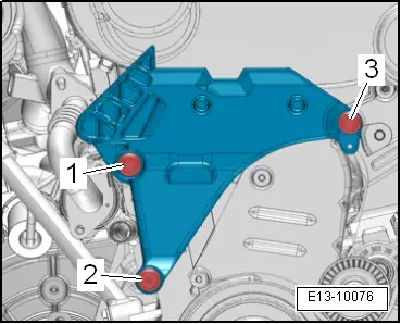
–  Unscrew the securing bolts of the engine support in the sequence -3 - 1-.
–  Remove engine bracket upwards.
Installing
Installation is in the reverse sequence of removal. Note the following:
  Caution
The tightening sequence and specified torques for the engine bracket securing bolts must always be followed. Otherwise the engine mount may be exposed to tensioning that will result in the engine mount breaking.
–  Insert engine bracket from above.
  Note
The securing bolt -1- is accessible through an aperture in the wheel housing. If necessary, raise and lower engine using spindle of support bracket -10 - 222 A- to remove or start bolts -2- and -3-.
–  First tighten new securing bolts hand-tight in sequence -1…3-.
  E13-10076
Tightening sequence for the engine bracket
–  Retighten securing bolts in tightening sequence to prescribed specified torque → Item.
  E13-10076
–  Fit the engine support and then tighten bolt -A- first and then bolt -C-. Tightening torque → Chapter
–  Using the spindle, establish contact between the engine support and the assembly mounting.
–  Apply and tighten the bolt -B-. Tightening torque → Chapter
Further assembly is basically the reverse of the dismantling sequence. Note the following:
t  Ensure that fuel hose connections are tight.
t  Do not interchange supply and return hose (return hose blue or blue markings, supply hose black).
  N10-10280

cylinder block: Assembly overview > < Belt routing: Assembly overview