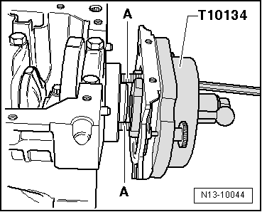
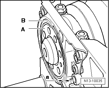
| The sealing flange is inserted along with the crankshaft sender wheel. |
| –
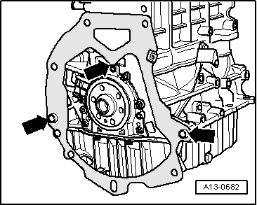
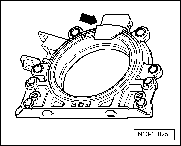
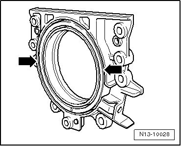
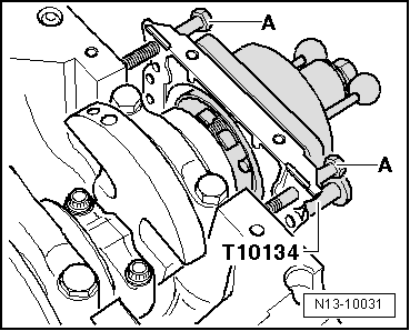
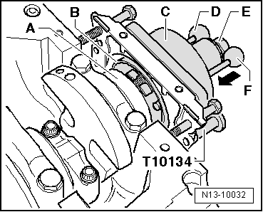
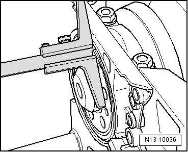
| For the reverse order: Turn the 3 M6x35 bolts maximum 1/2 rotations in the sealing flange -arrow- one after another. |
| –
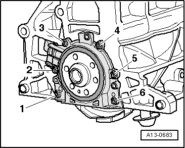
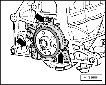
| Remove sealing flange together with sender wheel. |
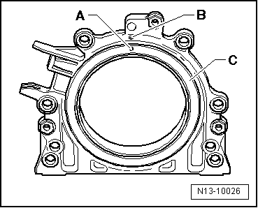
| Sealing flange, gearbox side: Fitting |

Note | t
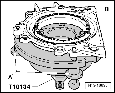
| The sealing flange with the PTFE seal is fitted with a pressure ring on the sealing lip. This pressure ring fulfils the function of an assembly sleeve and cannot be removed before fitting. |
| t
| Once unwrapped, do not separate the sealing flange and the sender wheel or modify the position. |
| t
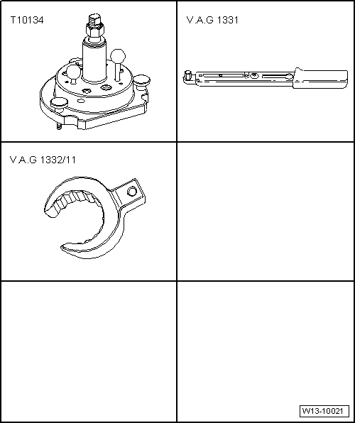
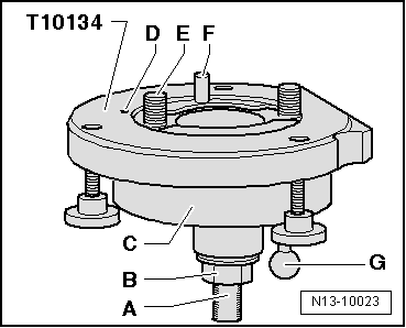
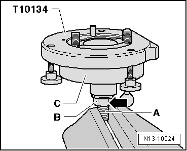
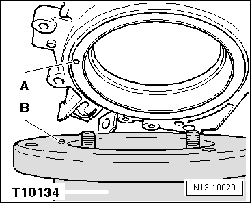
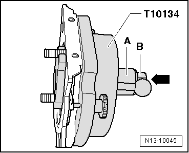
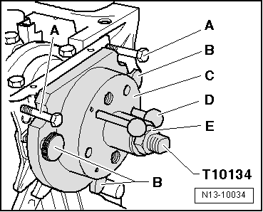
| The sender wheel is held in its installation position on the assembly device -T10134- by a locating pin. |
| t
| The sealing flange and the seal make up one inseparable component and can only be replaced along with the sender wheel. |
| t
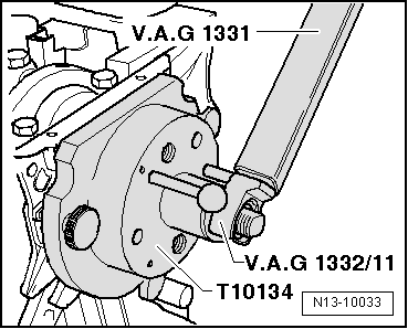
| The assembly tool -T10134- is held in its installation position for the crankshaft by a guide pin which is inserted into a hole on the crankshaft. |
|
|
|