seat Workshop Repair Guides

SEAT Workshop Service and Repair Manuals

Exhaust gas temperature regulation > < Installation position and specified torque of clamp
Exhaust gas recirculation radiator Removing and installing
t  Exhaust gas recirculation radiator Removing → Anchor
t  Exhaust gas recirculation radiator Installing → Anchor.
Consult the equivalence table for tools and equipment according to applicability among Seat / VW / Audi / Skoda → Chapter.
   
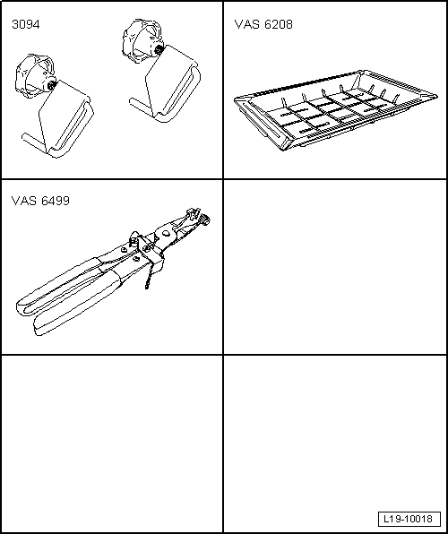
Special tools and workshop equipment required
t  Hose clamps -3094-, see equivalent → Anchor
t  Collecting tray -VAS 6208-, see equivalent → Anchor
t  Base -VAS 6499-, see equivalent → Anchor

   
Removing .
–  Remove the hose -1- from the vent on the crankshaft case. Press the unlocking buttons for this purpose.
–  Leave the vacuum hoses open -arrows-.
–  Remove air pipe from air filter housing; release hose clip -3- for this.
–  Unscrew bolt -2-, swing air pipe with inlet connection to rear and pull off from turbocharger.
  A21-10437
–  Unscrew bolts -arrows-.
–  Release the hose clip -1- and remove the vibration damper -2-.
–  Remove particulate filter → Chapter.
  A21-10478
–  Unscrew bolts and remove pipes -A- for exhaust gas recirculation.
  N15-10443
–  Unscrew bolts -1, 3-, union nut -2- and banjo bolts -4, 5-, and remove turbocharger support with oil supply line.
–  Place drip tray for workshop hoist -VAS 6208- beneath engine.
  A21-10502
–  Pinch off coolant hoses -1- and -3- with hose clamps -3094- and remove from exhaust gas recirculation cooler; loosen hose clamps for this.
–  Unplug connector -2-.
–  Remove vacuum hose -4- from vacuum unit and free.
–  Unscrew bolts -arrows- and remove exhaust gas recirculation cooler.
Fitting .
l  Tightening torque → Chapter
Installation is carried out in reverse order, noting the following:
  Note
t  Renew gaskets, seals and self-locking nuts.
t  Hose connections and air pipes and hoses must be free of oil and grease before assembly.
t  Secure all hose connections with the hose clips corresponding to original equipment → Electronic parts catalogue.
t  Reinstall heat insulation sleeve in original position when installing.
l  The sequence of the actions must be maintained so that a tension-free assembly of the combined flange (oil supply and oil return lines) is guaranteed together with the support of the exhaust gas turbocharger.
l  This also guarantees the tension free assembly of the exhaust gas turbocharger supports between the cylinder block and the exhaust gas turbocharger at the same time.
–  Fit the combined flange (oil supply and oil return lines) to the exhaust gas turbocharger and cylinder block together with the support of the exhaust gas turbocharger.
–  Fit the oil return line to the exhaust gas turbocharger and cylinder block.
  A26-10879
–  First bring the bolts -1- and the hollow bolt -4- of the exhaust gas turbocharger on the cylinder block by hand.
–  Fix the screw -3- to the turbocharger.
–  Then move the union nut-2- and the banjo bolt -5- for the oil supply line.
–  Then insert the bolt -1- → Item, the banjo bolt -4- in the cylinder block → Item and tighten the support of the exhaust gas turbocharger -3- → Item one after another and in several stages to the specified tightening torque.
–  Finally, tighten the screw of the clip of the oil supply line / support of the exhaust gas turbocharger.
Tightening torques → Chapter
  A21-10502
–  Install connecting pipes -A- for exhaust gas recirculation → Chapter.
–  Installing support for turbocharger with oil supply line, inlet connection and impulse absorber → Chapter.
–  Mount air intake hoses with screw clamps → Fig..
–  Install particulate filter → Chapter.
–  Check oil level → Chapter.
–  Check coolant level → Chapter.
  Note
After fitting the turbocharger, allow the engine to run at idle for about 1 minute, without accelerating; this will lubricate the turbocharger.
  N15-10443

Exhaust gas temperature regulation > < Installation position and specified torque of clamp