seat Workshop Repair Guides

SEAT Workshop Service and Repair Manuals

Servicing valve gear > < Sealing flange and flywheel / drive plate: Removing and installing
Removing and installing camshaft timing chain
   
Removing and installing camshaft timing chain
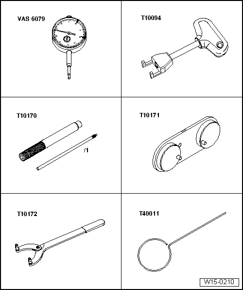
Special tools and workshop equipment required
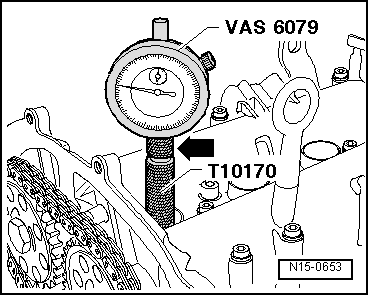
t  Gauge -VAS 6079-, see equivalent → Anchor
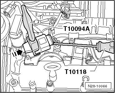
t  Extraction tool -T10094 A-, see equivalent → Anchor
t  Dial gauge adaptor -T10170-, see equivalent → Anchor
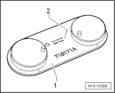
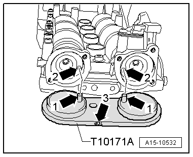
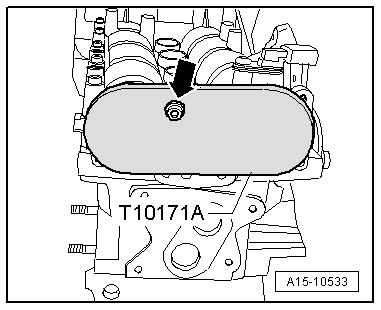
t  Camshaft clamp -T10171 A-, see equivalent → Anchor.
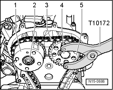
t  Hose clamp -T10172-, see equivalent → Anchor
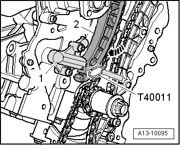
t  Pin -T40011-, see equivalent → Anchor

   
t  Spark plug spanner -3122 B-, see equivalent → Anchor
  W00-0060
t  Locking pin -T10340-, see equivalent → Anchor.
  Note
  W00-10414
t  Camshaft clamp -T10171- can also be used instead of camshaft clamp -T10171 A- if an additional hole is drilled as described below.
t  Place drilling template -1- onto camshaft clamp -T10171- as shown in illustration.
t  Apply a centre punch mark at marking -2-.
t  Use a Ø 7 mm drill bit to drill a hole at position marked and deburr hole.
t  Apply identification marking „T10171 A“ to tool
Camshaft timing chain: Removing → Anchor
Camshaft timing chain: Fitting → Anchor
Removing
Proceed as follows:
–  Remove poly V-belt → Chapter.
  N15-10368
–  Disengage coolant hose -1- at engine cover panel.
–  Pull out the dipstick.-2-.
–  Unscrew bolts -arrows- and remove engine cover panel.
  E21-10047
–  Unscrew bolts -2- and detach retaining bracket -1-.
–  Unplug the electrical connector -3- at charge pressure sender -G31-.
–  Release retainers -arrows- and detach air pipe first from throttle valve module -J338- and then from turbocharger.
–  Move hoses on air pipe clear.
  A21-10169
–  Detach vacuum lines -2- and -3-.
  Note
Disregard -items 1, 4- and -arrow-.
  A13-10522
–  Apply the extractor -T10094 A- on the ignition coil -arrow-, using theExtractor -T10118-, pull out ignition coil and at the same time unplug electrical connector at ignition coil for cylinder 1 ... 4.
–  Remove spark plug for cylinder 1 with spark plug socket and extension -3122 B-.
  N28-10066
–  Unplug electrical connectors -1, 2, 4-, detach wiring duct -3- from camshaft housing and swivel to left side.
  A15-10538
–  Unplug the electrical connector -arrow- on the oil pressure switch -F1-.
  A17-10341
–  Remove bolt -1- for earth wire.
  Note
Disregard -arrows-.
  A19-10615
–  Remove bolts -1- and -2- and press coolant pipes (left-side) to left side).
  Note
Disregard -arrows-.
  A19-10616
–  Remove bolts -arrows- and detach sealing caps -1- and -2-.
  A15-10531
–  Screw adapter for dial gauge -T10170- into spark plug hole as far as the stop.
–  Insert dial gauge -VAS 6079- with extension -T10170/1- as far as the stop and secure using locking nut -arrow-.
–  Rotate crankshaft in normal direction of rotation to „TDC“.
l  „TDC“ = maximum measured value on dial gauge.
  N15-0653
l  The threaded holes -arrows- in the camshafts must be positioned as shown in illustration. Turn crankshaft one turn (360°) if necessary.
  N15-0657
–  Insert camshaft clamp -T10171 A- into holes in camshafts as far as stop.
l  The locking pins -arrows 1- must engage in the holes -arrows 2-.
l  The marking „TOP“-arrow 3- should be legible from above.
  A15-10532
–  To secure the camshaft clamp -T10171 A-, screw in an M6 bolt -arrow- by hand, but do not tighten.
  Caution
Avoid damage to camshafts.
The camshaft clamp -T10171 A- must not be used as a counterhold tool.
  A15-10533
–  Remove bolts -1- and -3- and take off bracket -2- for coolant pipe (right-side).
  A15-10539
–  Unscrew plug -arrow- for „TDC“ hole on cylinder block.
  A13-10524
–  Screw locking pin -T10340- into cylinder block as far as stop and tighten to 30 Nm.
  Note
The locking pin -T10340- locks the crankshaft only in the direction of engine rotation.
  A13-10525
  Caution
Risk of damage to engine.
To prevent the crankshaft chain sprocket from slipping off the drive lug, do not rotate the crankshaft after the poly V-belt pulley has been detached.
–  Loosen the bolt for the poly V-belt pulley, for this purpose, counterhold using the counterhold tool -3415- with dowel pin -3415/1-.
–  Remove the bolt and take off the poly V-belt pulley.
–  Remove distribution chain → Chapter.
  N13-0469
–  Insert bush -2- and screw in crankshaft pulley bolt -1- hand-tight to secure chain sprocket on crankshaft.
  A13-10093
–  Press tensioning rail -2- in direction of -arrow- and use locking pin -T40011- to lock piston for chain tensioner -1-.
  Caution
If a used timing chain rotates in the opposite direction when it is refitted, this can cause breakage.
Mark running direction of timing chain with coloured arrows for re-installation. Do not mark timing chain by means of centre punch, notch or the like.
Avoid damage to camshafts.
The camshaft clamp -T10171 A- must not be used as a counterhold tool.
Risk of damage to thread.
The camshaft adjuster central bolt has a left-hand thread.
  A13-10095
–  Loosen bolt -2- for camshaft adjuster -1- and bolt -4- for camshaft chain sprocket -5-, using counterhold tool -T10172- to counterhold on camshaft chain sprocket.
–  Detach camshaft chain sprocket together with camshaft timing chain -3-.
  Note
Leave the camshaft adjuster on the camshaft.
Installing
l  Tightening torques → Chapter
  Note
t  Renew bolts for camshaft chain sprocket and camshaft adjuster.
t  Renew gaskets and O-rings for camshaft sealing caps.
  N15-0686
–  Check „TDC“ position of camshaft and crankshaft:
l  The camshaft clamp -T10171 A- must be fitted to camshaft housing.
  Caution
Risk of damage to valve gear.
The camshafts must not be moved axially when turning.
  A15-10533
l  Locking pin -T10340- screwed into cylinder block as far as stop and tightened to 30 Nm.
l  Turn crankshaft in direction of engine rotation until it makes contact with locking pin -T10340-.
  Caution
Risk of damage to thread.
The camshaft adjuster central bolt has a left-hand thread.
  A13-10525
–  Fit bolt -2- for camshaft adjuster -1- without tightening.
l  It should just be possible to turn the adjuster on the camshaft without axial movement.
  A15-10534
–  Fit camshaft timing chain according to marks applied when removing.
–  Fit camshaft timing chain -1- together with chain sprocket -2- for exhaust camshaft onto crankshaft sprocket and camshaft adjuster.
–  Fit bolt -3- for camshaft chain sprocket without tightening.
l  It should just be possible to turn the camshaft chain sprocket on the camshaft without axial movement.
  A15-10535
–  Remove locking pin -T40011- from chain tensioner -1- and tension camshaft timing chain.
–  Check „TDC“ position of camshaft and crankshaft again → Anchor.
  A13-10095
  Caution
Risk of damage to thread.
The camshaft adjuster central bolt has a left-hand thread.
–  Tighten bolt -2- for camshaft adjuster -1- to 40 Nm and bolt -4- for camshaft chain sprocket -5- to 50 Nm, using counterhold tool -T10172- to counterhold on camshaft chain sprocket.
  Note
t  Do not tighten bolts for camshaft adjuster and camshaft chain sprocket to final torque before checking timing again.
t  When tightening the bolts, the crankshaft must not turn and the camshaft timing chain -3- must remain tensioned on both sides.
–  Detach camshaft clamp -T10171 A-.
–  Remove locking pin -T10340-.
  N15-0686
–  Turn crankshaft 2 revolutions in direction of engine rotation and set to „TDC“.
l  „TDC“ = maximum measured value on dial gauge.
  Note
t  If the crankshaft was turned more than 0.01 mm beyond „TDC“, turn back the crankshaft approx. 45° in the opposite direction of normal rotation. Then turn crankshaft in normal direction of rotation to „TDC“.
t  Permissible deviation from TDC:  ±  0.01 mm.
t  -Arrow- can be disregarded.
  N15-0653
–  Screw locking pin -T10340- into cylinder block as far as stop and tighten to 30 Nm.
–  Turn crankshaft in direction of engine rotation until it makes contact with locking pin.
  A13-10525
–  Insert camshaft clamp -T10171 A- into holes in camshafts as far as stop.
l  The locking pins -arrows 1- must engage in the holes -arrows 2-.
l  The marking „TOP“-arrow 3- should be legible from above.
–  If camshaft clamp -T10171 A- cannot be fully inserted into holes in camshafts, repeat adjustment.
–  If it is possible to insert camshaft clamp -T10171 A- completely, take off camshaft clamp again.
–  Remove locking pin -T10340-.
  A15-10532
  Caution
Risk of damage to thread.
The camshaft adjuster central bolt has a left-hand thread.
–  Tighten bolt -2- for camshaft adjuster -1- and bolt -4- for camshaft chain sprocket -5- and turn through specified angle to final setting (counterhold at camshaft chain sprocket using counterhold tool -T10172-).
  Note
Ignore -item 3-.
–  Turn crankshaft 2 revolutions in direction of engine rotation and set to „TDC“.
–  Check adjustment → Anchor, repeat adjustment if necessary.
  Caution
Risk of damage to engine.
To prevent the crankshaft chain sprocket from slipping off the drive lug, do not rotate the crankshaft after the poly V-belt pulley has been detached.
  N15-0686
–  Remove the bolt -1- for the poly V-belt pulley.
  Note
Leave bush -2- in position on crankshaft.
The remaining installation steps are carried out in reverse sequence - note the following points:
–  Install timing chain cover (right-side) → Chapter.
–  Lubricate O-rings for camshaft sealing caps with oil before installing.
–  Install poly V-belt pulley for crankshaft → Chapter.
–  Renew the seal on the screw plug for „TDC“.
  A13-10093
–  Tighten the screw plug for „TDC“-arrow- to 30 Nm.
–  Install coolant pipes (left-side) → Chapter.
–  Install spark plug → Booklet101.
–  Install air pipe → Chapter.
–  Install engine cover → Chapter.
–  Install poly V-belt → Chapter.
  A13-10524

Servicing valve gear > < Sealing flange and flywheel / drive plate: Removing and installing