| –
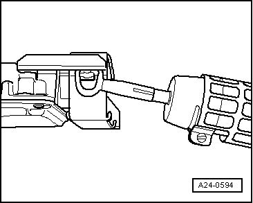
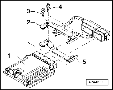
| The two shear bolts screwed into the engine control unit do not need to be heated. They must be removed without being heated. |
| –
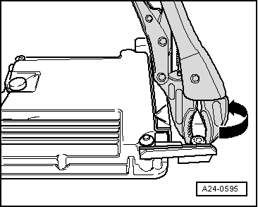
| Detach metal locking plate from control unit connectors. |
| –
| Disengage and remove the engine control unit -J623- connector. |
| –
| Remove engine control unit -J623-. |
| Install in reverse order to dismantling, noting the following: |
| –
| After installation, the locking plate must be re-fitted on the engine control unit -J623-. |
| –
| Remove the remains of the threadlocker from the breakaway bolt holes. The threads can be cleaned with a thread tap. |
| –
| Always use new shear bolts. |
| –
| Activate engine control unit via vehicle diagnostic, testing and information system -VAS 505X- in „Guided Functions“ mode, „Replace engine control unit“. |
| –
| Take vehicle for a test drive. |
|
|
|
 Note
Note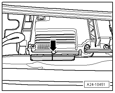
 WARNING