| t
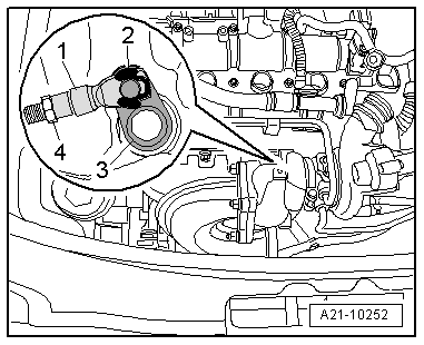
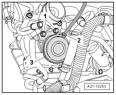
| If the theoretical value is not obtained, loosen the lock nut -4-. |
| t
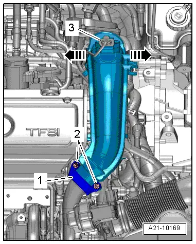
| Lever off safety washer -2-, then remove threaded part -1- on the control level rod -3-. |
| t
| Turn the threaded part on the control rod until the theoretical value is reached. To check, connect the threaded part to the control lever rod. |
| t
| Secure the threaded part with the safety washer -2- on the control lever rod and tighten the counter nut -4-. |
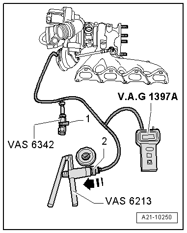
| Check the setting of the pressure capsule |
| –
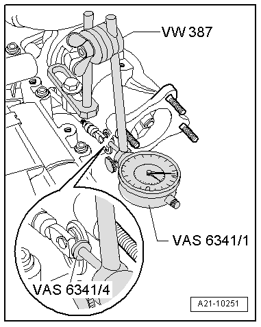
| At 0 bar, tense the gauge -VAS 6341/1- to 1 mm. |
| –
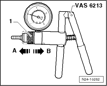
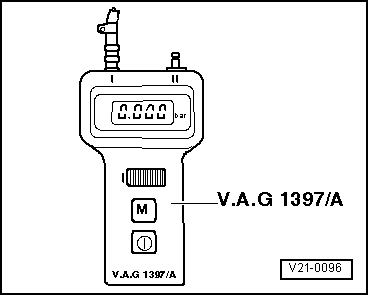
| Activate the manual vacuum pump -VAS 6213- several times until a pressure of 750 ... 800 mbar is shown on the turbocharger dial gauge -V.A.G 1397A-. |
| –
| Release pressure in the pressure control valve -VAS 6342- to 375 mbar. |
| –
| Read and note the value indicated by the gauge -VAS 6341/1-. |
| –
| Release pressure in the pressure control valve -VAS 6342- to 0 mbar. |
| –
| Activate the manual vacuum pump -VAS 6213- several times until a pressure of 375 mbar is shown on the turbocharger dial gauge -V.A.G 1397A-. |
| –
| Read and note the value indicated by the gauge -VAS 6341/1-. |
| –
| Calculate average value; by adding values „1“ and „2“ and dividing by 2. |
| –
| Activate the manual vacuum pump -VAS 6213- several times until a pressure of 750 ... 800 mbar is shown on the turbocharger dial gauge -V.A.G 1397A-. |
| –
| Release pressure in the pressure control valve -VAS 6342- to 475 mbar. |
| –
| Read and note the value indicated by the gauge -VAS 6341/1-. |
| –
| Release pressure in the pressure control valve -VAS 6342- to 0 mbar. |
| –
| Set the dial gauge -VAS 6341/1- indicator to "0". |
| –
| Activate the manual vacuum pump -VAS 6213- several times until a pressure of 475 mbar is shown on the turbocharger dial gauge -V.A.G 1397A-. |
| –
| Read and note the value indicated by the gauge -VAS 6341/1-. |
| –
| Calculate average value; by adding values „1“ and „2“ and dividing by 2. |
| –
| Repeat adjustment procedure if readings do not match specifications → Anchor. |
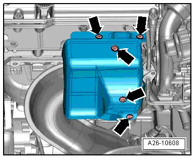
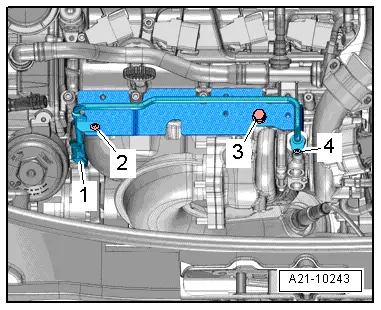
| Tightening torque of the heat protection plate for the exhaust gas turbocharger: 10 Nm |
| Install in the reverse order to removal. |
| –
| Mount the primary catalytic converter with exhaust pipe → Chapter. |
|
|
|

 Note
Note
 Caution