
Leon Mk1
 Note
Note
|
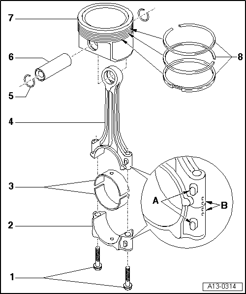
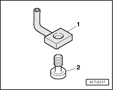
| 1 - | Conrod bolt, 30 Nm +90° (1/4 turn) |
| q | replace |
| q | Oil threads and contact surface. |
| q | Use old bolts when measuring radial clearance |
| q | When measuring radial clearance, tighten to 30 Nm but do not turn further |
| 2 - | Conrod bearing cap |
| q | Mark cylinder number -B- |
| q | Fitting position: The marks -A- should point towards the pulley |
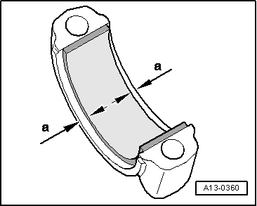
| 3 - | Bearing shells |
| q | upper bearing shell with oil drilling for piston pin lubrication |
| q | Installation position → Fig. |
| q | Do not interchange used bearing shells (mark). |
| q | Axial play, new: 0,10 ... 0.35 mm; wear out limit: 0.40 mm |
| q | Checking radial clearance with Plastigage: new: 0,01 ... 0.05 mm; wear out limit: 0.12 mm when measuring the radial play, do not rotate the crankshaft |
| 4 - | Conrod |
| q | Can only be used as one unit |
| q | Mark cylinder number -B- |
| q | Fitting position: The marks -A- should point towards the pulley |
| q | With oil drilling for piston pin lubrication |
| 5 - | Circlip |
| 6 - | Piston pin |
| q | If difficult to move, heat piston to approx. 60 °C |
| q | Remove and install with the installation tool -VW 222A-, see equivalent → Anchor |
| 7 - | Piston |
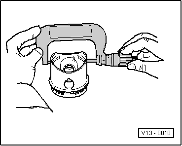
| q | check → Fig. |
| q | Mark installation position and cylinder number. |
| q | Arrow on piston crown points to pulley end |
| q | Install using piston ring clamp |
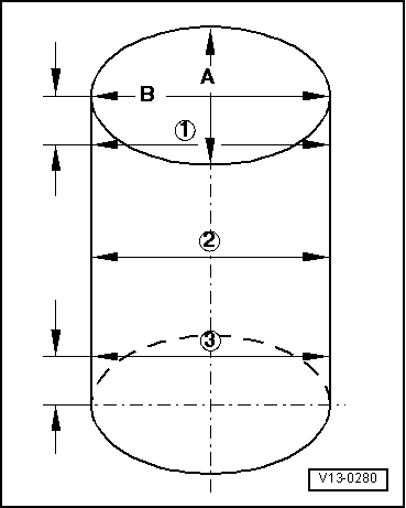
| q | Piston and cylinder dimensions → Chapter |
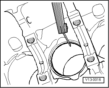
| q | Checking cylinder bore → Fig. |
| 8 - | Piston rings |
| q | Displace the gaps at 120° from each other |
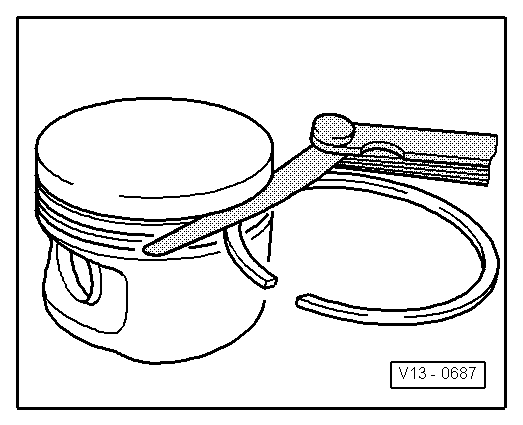
| q | Use piston ring pliers to remove and install |
| q | „TOP“ must face towards piston crown |
| q | Checking the play between the piston rings → Fig. |
| q | Checking ring-to-groove clearance → Fig. |
| Piston ring (in mm) | new | Wear limit |
| 1. compression ring | 0,20 … 0,40 | 0,8 |
| 2. compression ring | 0,20 … 0,40 | 0,8 |
| Oil scraping ring | 0,25 … 0,50 | 0,8 |
|
|
| Piston ring (in mm) | new | Wear limit |
| 1. compression ring | 0,06 … 0,09 | 0,20 |
| 2. compression ring | 0,05 … 0,08 | 0,20 |
| Oil scraping ring | 0,03 … 0,06 | 0,15 |
|
|
|
|
|
|
|
|