
Leon Mk1
| Overview of fitting locations |
| Components A to F are not shown in the exploded view of components. |
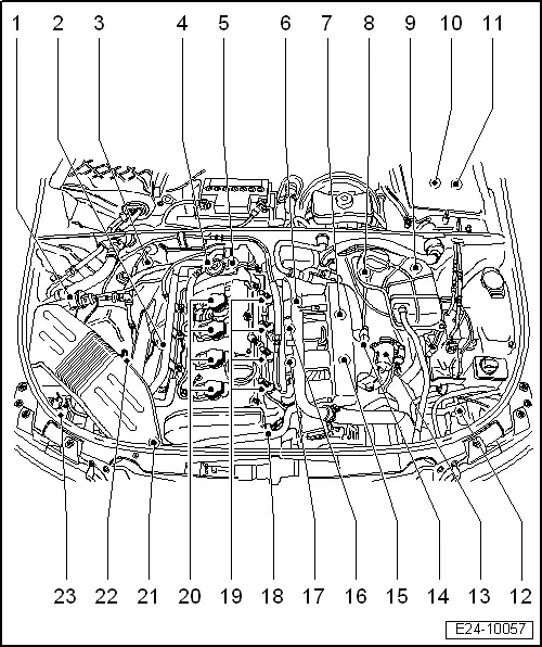
| A - | Brake light switch - F- and brake pedal switch -F63- |
| q | Fitting location → Fig. |
| B - | Diagnostic connector |
| q | On the roller muffler, on the driver's side |
| C - | Fuel pump fuse: |
| q | In the electrical micro controller behind the shelf on the drivers side |
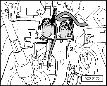
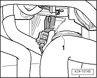
| D - | Checking clutch pedal switch -F36- |
| q | Fitting location → Fig. |
| E - | Accelerator position sender -G79- and accelerator position sender 2 -G185- |
| q | On the accelerator pedal (both senders are located in the housing) |
| F - | Warning light „EPC“ |
| q | On the instrument panel |
| 1 - | Activated charcoal filter solenoid valve 1 -N80- |
| 2 - | Lambda probe -G39- and Lambda probe heater -Z19- |
| q | Fitting location → Fig. |
| q | Removing and installing → Chapter |
| 3 - | Lambda probe, after catalytic converter -G130- and Lambda probe heater 1, after catalytic converter -Z29- |
| q | Fitting location → Fig. |
| q | Removing and installing → Chapter |
| 4 - | Combination valve for secondary air system |
| q | check → Chapter |
| q | Removing and installing → Chapter |
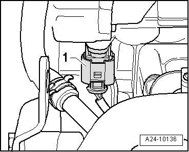
| 5 - | Coolant temperature sender -G62- |
| q | Fitting location → Fig. |
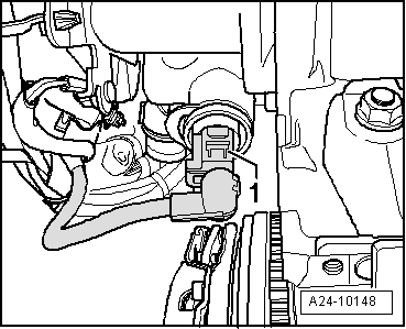
| 6 - | Engine speed sender -G28- |
| q | Fitting location → Fig. |
| 7 - | Secondary air inlet valve -N112- |
| q | Fitting location → Fig. |
| q | Green connector |
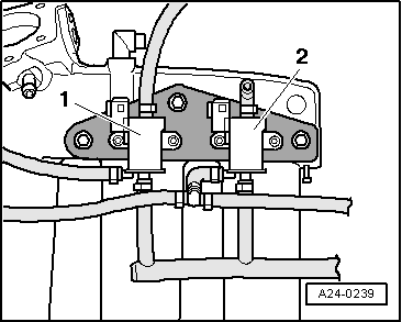
| 8 - | Bracket for electrical connectors |
| q | Fitting location → Fig. |
| q | You can access from one side after releasing the coolant expansion tank. |
| 9 - | Bracket for electrical connectors |
| q | Fitting location → Fig. |
| q | You can access from one side after releasing the coolant expansion tank. |
| 10 - | Electronics box in plenum chamber |
| q | Installation location of the Motronic control unit -J220- with integrated altitude sender -F96- |
| q | Installation location of the Motronic current supply relay -J271- |
| 11 - | Electronics box in plenum chamber |
| q | Installation location of the secondary air pump relay -J299- |
| 12 - | Charge air pressure sender -G31- |
| q | Fitting location → Fig. |
| q | Removing and installing → Chapter |
| 13 - | Throttle valve module -J338-, throttle valve drive (electric throttle operation) -G186- |
| q | With angle sensor 1 for throttle valve drive with electrical accelerator actuation -G187- and angle sensor 2 for throttle valve drive with electrical accelerator actuation -G188- |
| q | The engine control unit must be re-adjusted after replacing the throttle valve control unit -J338-. |
| 14 - | Intake air temperature sender -G42- |
| 15 - | Turbocharger air recirculation valve -N249- |
| q | Fitting location → Fig. |
| 16 - | Knock sensor I -G61- |
| q | For cylinder 1 and 2 |
| q | Tightening torque: 20 Nm |
| 17 - | Knock sensor 2 -G66- |
| q | For cylinder 3 and 4 |
| q | Tightening torque: 20 Nm |
| 18 - | Hall sender -G40- (camshaft position sensor) |
| q | Fitting location → Fig. |
| 19 - | Injectors |
| q | Cylinder 1 injector -N30- |
| q | Cylinder 2 injector -N31- |
| q | Cylinder 3 injector -N32- |
| q | Cylinder 4 injector -N33- |
| 20 - | Ignition coils with output stage |
| q | Ignition coil 1 with output stage -N- |
| q | Ignition coil 2 -N128- |
| q | Ignition coil 3 -N158- |
| q | Ignition coil 4 -N163- |
| q | Removing and installing → Chapter |
| 21 - | Charge pressure control solenoid valve -N75- |
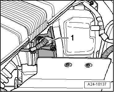
| 22 - | Air mass meter -G70- |
| q | Fitting location → Fig. |
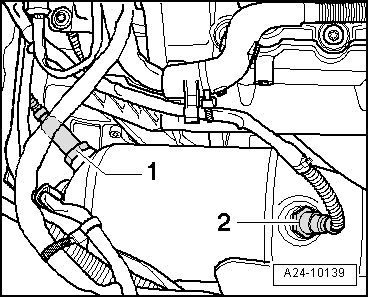
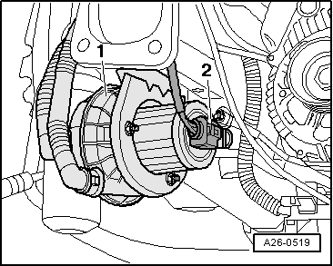
| 23 - | Secondary air pump motor -V101- |
| q | Fitting location → Fig. |
| q | Removing and installing → Chapter |
|
|
|
|
|

|
 Note
Note
|
|
|
|
|
|
|
|
Note
|
|