seat Workshop Repair Guides

SEAT Workshop Service and Repair Manuals

Check the pressure capsule for the exhaust gas turbocharger (engine code BWA) > < Part III:
Remove and install the exhaust gas turbocharger (engine code BWA)
t  Removing → Anchor
t  Installing → Anchor
t  Tightening torques → Anchor
Consult the equivalence table for tools and equipment according to applicability among Seat / VW / Audi / Skoda → Chapter.
Special tools and workshop equipment required
   
t  Pliers for spring-loaded band-type clamps -VAS 6499-, see equivalent → Anchor
  W00-10700
t  
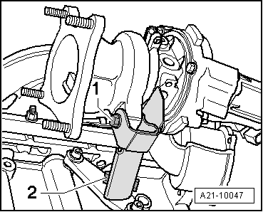
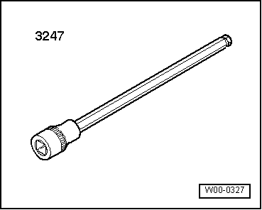
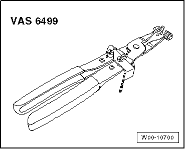
Socket -3247-, see equivalent → Anchor
  Caution
If a mechanical fault is detected on the turbocharger, for example, a broken blade wheel, changing the turbocharger is not enough. To avoid subsequent damage, carry out the following operations:
t  
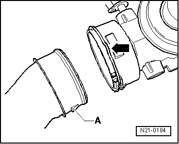
Ensure that the air filter housing, the cartridge and the vacuum hoses are not dirty.
t  Ensure that there are no foreign bodies in the supercharger air circuit and the intercooler.
If foreign matter is found in the charge air system, clean all relevant ducts and hoses and renew the charge air cooler if necessary.
Removing
–  Remove engine cover panel → Chapter.
–  Drain coolant → Chapter.
–  Remove the grille below the windscreen → Body, exterior assembly work; Rep. gr.55.
–  Remove the front plate of the plenum chamber → Bodywork exterior fitting work; Rep. gr.55.
  W00-0327
–  Remove noise insulation on the right side.
  A10-1643
–  Disconnect the air duct -arrow- of the intercooler.
  A21-10050
–  Loosen the bolts -arrows-, and remove the supercharger air pipe.
  A21-10030
–  Disconnect the connectors -1 and 2-. Loosen the bolts -arrows-, and remove the turbocharger hose.
  N21-10043
–  Disconnect the connector of the Lambda probe -G39--arrow-, and set the cable aside.
  A26-10134
–  Disconnect the connectors -1- of the ignition coils, and leave the cable harness to aside.
  A15-10137
–  Separate the coolant piping towards the coolant expansion tank -flecha-.
  A21-10043
–  Disconnect the coolant hoses -1- and -2-.
–  Loosen the coolant piping -3- .
  A21-10042
–  Remove the top coolant hose towards the heat exchanger -arrow-.
  N21-10045
–  Loosen the coolant piping protector plate -arrows-.
  A21-10041
–  Loosen the engine block breather hose with heat shield from the turbocharger -1-.
–  Release the engine block breather hose -2- from the cylinder head cover, and remove it.
–  Release the activated carbon filter hose which leads to the turbocharger from the cylinder head cover -3-.
–  Loosen the turbocharger oil supply piping -4-.
–  Remove drive shaft (right-side) → Rep. gr.40.
  A21-10032
–  Loosen the 2 top securing bolts of the primary exhaust pipe/turbocharger.
Four wheel drive vehicles
  N26-10097
–  Remove the heat protection plate above the cardan shaft using the socket -3247-.
Vehicles with front-wheel drive
  A10-10260
–  Unbolt heat shield for right-hand side driveshaft -arrows-.
Continued for all vehicles
  A10-1633
–  Loosen the 2 top securing bolts of the primary exhaust pipe/turbocharger.
  N26-10097
–  Unbolt exhaust system retainer -arrow-.
  A10-1632
–  Remove the exhaust system by the surrounding sleeve -arrows-.
–  Release the primary exhaust pipe from the turbocharger, and move it slightly backwards.
  Note
Do not remove the catalytic converter or disconnect the Lambda probe.
  A10-1734
–  Loosen the oil supply piping and the coolant supply piping -arrows-.
  N15-10166
–  Remove the oil return pipe -arrows- from the turbocharger.
  A21-10048
–  Loosen the bolts -1- and -2-, and remove the turbocharger bracket.
  A21-10047
–  Disconnect the coolant tube-arrow-.
  Note
The nuts of the securing strip must not be loosened.
  A21-10036
–  Loosen the nut -1- of the coolant pipe, and loosen the top nuts -arrows-.
–  Remove the intake manifold/turbocharger upwards.
Installing
Installation is carried out in the reverse order; noting the following in the process:
t  Always replace seals, gaskets and self-locking nuts.
t  Fill turbocharger with engine oil at oil supply pipe connection.
t  After fitting the exhaust gas turbocharger, allow the engine to run at idle for 1 min to ensure turbocharger oil supply.
t  The coolant return pipe → Item must be fitted together with the turbocharger.
t  The couplings and air hoses of the supercharging system must be free from oil and grease before assembling.
t  Secure the hose connections with original clamps.
–  Install the exhaust system, and adjust it without tension → Chapter.
–  Fit the half shafts → Rep. gr.40.
  A21-10096
–  When installing air pipes with connector elements, ensure that the securing clip -arrow- engages audibly on the retaining lug -A-.
–  Check the oil level.
–  Fill up with coolant → Chapter.
Tightening torques
  N21-0184
Qty. Nm
Exhaust manifold/turbocharger to cylinder head20 → Remark
Oil supply pipe to the turbocharger30
Turbocharger bracket to engine block30 → Remark
Turbocharger bracket to turbocharger30 → Remark
Right hand side supercharger air tube to the oil sump10

1)  Renew nuts.
2)  Locking fluid for hot working bolts → Parts catalogue
   

Check the pressure capsule for the exhaust gas turbocharger (engine code BWA) > < Part III: