seat Workshop Repair Guides

SEAT Workshop Service and Repair Manuals

Reading out and erasing the engine control unit event memory > < Removing and installing engine control unit
Engine control unit with antitheft protection: removing and fitting
t  Removing → Anchor
t  Installing → Anchor
Consult the equivalence table for tools and equipment according to applicability among Seat / VW / Audi / Skoda → Chapter.
Special tools and workshop equipment required
   
t  Electric knife -VAG 1561A-, see equivalent → Anchor
t  Saw set -VAG 1561/14-, see equivalent → Anchor
  W00-0532
t  
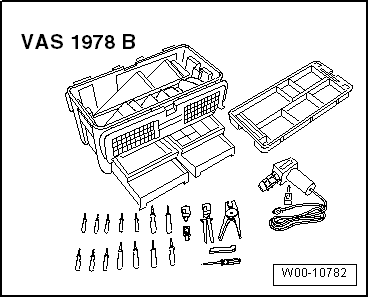
Hot air gun from cable repair set -VAS 1978B-, see equivalent → Anchor
t  Pliers
  Note
To replace the engine control unit, connect the central diagnosis -VAS 5051B- or central diagnosis -VAS 5052- and complete the guided function „Replace control unit“.
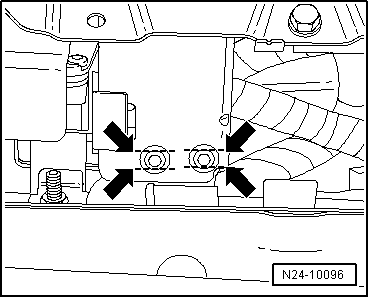
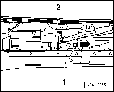
Removing
–  Switch ignition OFF.
–  Remove the front panel of the plenum chamber → Bodywork, exterior fitting work; Rep. gr.50.
  Note
The thread on the breakaway bolts has been treated with a threadlocker. The effect of the threadlocker is reduced by heating the breakaway bolts with a hot air gun.
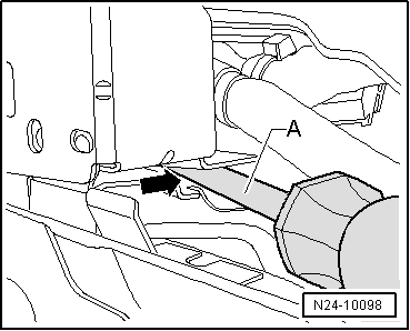
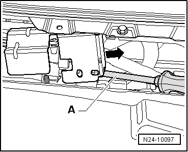
  Caution
Cover the cables, connectors and control units close to the engine control unit to prevent them from burning.
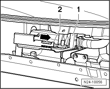
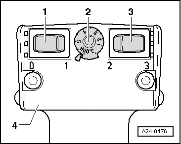
Carry out the adjustments on the hot air blower -4- as described below:
  W00-10782
–  Turn temperature setting potentiometer -2- to maximum heat output (600°C).
–  Set the two-level switch for air flow -3- to position 3.
  WARNING
When heating the headless bolts, other parts of the protective shell are also heated considerably. Wear protective gloves to avoid burns.
–  Place the nozzle of the hot air blower near the headless bolt.
–  Turn on the hot air blower and heat the bolts.
–  Loosen the bolts using pliers.
  Note
  A24-0476
If the bolts cannot be loosened, the heads of the split bolts must be sawn to create two flat parallel surfaces -arrows-, after which they can be loosened.
–  Loosen the bolts using pliers.
  N24-10096
–  Insert a screwdriver -A- between the protective cover and the retention plate -arrow-.
  N24-10098
–  Lift the protective cover by levering it with a screwdriver -A-, and remove it from the retention plate sideways -arrow-.
  N24-10097
–  Release front connector -1- from engine control unit and pull it off.
–  Lever up catch -2- slightly.
–  Then push engine control unit out of retainer -arrow-.
–  Release and unplug the rear connector on engine control unit.
Installing
–  Fit rear connector to engine control unit and lock in position.
–  Push engine control unit onto bracket.
–  Fit front connector to engine control unit and lock it in position.
–  Mount the protective cover on the retention plate.
  N24-10056
–  Tighten the headless bolts -1- evenly, until the bolt heads break off.
–  Remove the front panel of the plenum chamber → bodywork, exterior fitting work; Rep. gr.50.
  N24-10055

Reading out and erasing the engine control unit event memory > < Removing and installing engine control unit