seat Workshop Repair Guides

SEAT Workshop Service and Repair Manuals

Enginecrankshaft group, pistons > < Engine assembly mountings
Engine: fitting
Engine: fitting
   
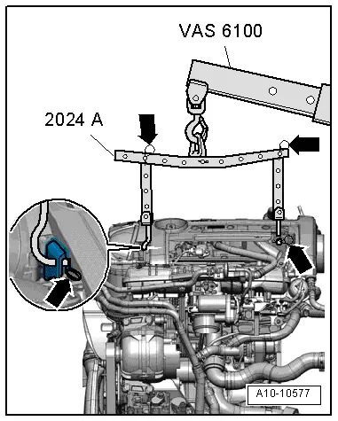
–  Attach lifting tackle -2024A- to engine and workshop hoist -VAS 6100- as shown in illustration.
Engine brackets → Chapter.
Installation is carried out in reverse sequence; note the following:
  Caution
When doing any repair work, especially in the engine compartment, pay attention to the following due to the cramped conditions:
t  Route all the various lines (e.g. for fuel, hydraulics, active carbon filter system, coolant, refrigerant, brake fluid and vacuum pipes and hoses) and electrical wiring so that the original positions are restored.
t  To avoid damage to lines/wiring, ensure sufficient clearance to all moving or hot components.
Vehicles with manual gearbox:
–  Use new dowel sleeves to centre the engine/gearbox assembly in the engine block.
  A10-10577
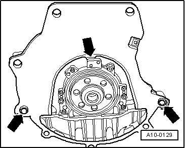
–  Hook intermediate plate onto sealing flange and slide onto dowel sleeves -arrows-.
–  Lubricate the splines of the driveshaft slightly with lubricant → Parts catalogue.
–  Clutch and clutch mechanism: checking and fitting → Manual gearbox; Rep. gr.30
Vehicles with automatic gearbox 0AM
  A10-0129
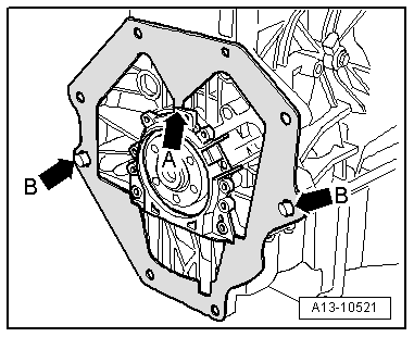
–  Ensure that the intermediate plate is hooked to the sealing flange -arrow A- and pushed onto dowel sleeves -arrow B-.
All vehicles (continued):
–  When mounting the engine / gearbox, ensure that there is sufficient free space in relation to the subframe as well as the radiator.
–  Align the engine position tension free by carrying out shaking moments or, if necessary, release the engine mount on the assembly.
–  Install pendulum support.
  Note
t  Engine assembly mounting tightening torques → Chapter
t  Electrical connections and routing → Electrical system; Rep. gr.97
–  Fit the primary exhaust pipe with catalytic converter → Chapter.
–  Install the right and left hand side drive shafts: → Running gear, axles, steering; Rep. gr.40.
–  Fit the supercharger air system hoses and observe the assembly instructions → Chapter.
Vehicles with manual gearbox:
–  Fit the gear selection mechanism and adjust, if necessary → Manual gearbox; Rep. gr.34
–  Mount the slave cylinder of the hydraulic clutch → Manual gearbox; Rep. gr.30.
Vehicles with automatic gearbox 0AM
–  Mount the control wire of the selector lever.
  Note
  A13-10521
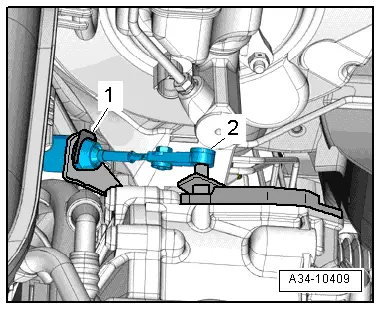
Due to the internal loss of its spring force, the safety ring for the selector lever control cable -1- always has to be replaced
–  Always set the selector lever control cable → 7 gear dual clutch automatic gearbox 0AM; Rep. gr.34
–  Fit the selector lever control cable and adjust, if necessary → Automatic gearbox 0AM; Rep. gr.34
All vehicles (continued):
–  Mount the soundproofing sump.
–  Fit the front panel of the plenum chamber → Bodywork, exterior fitting work; Rep. gr.50.
–  Fill coolant system with coolant → Chapter.
–  Connect battery → Electrical system; Rep. gr.27.
–  Adjust the engine control unit → Vehicle diagnostic tester„Guided operation“.
–  Perform test drive, and interrogate fault memory afterwards.
Tightening torques:
  A34-10409
Bolt union Tightening torque
Bolts, nutsM 610 Nm
 M 715 Nm
 M 822 Nm
 M10:40 Nm
 M1265 Nm


Enginecrankshaft group, pistons > < Engine assembly mountings