
Leon Mk1
|
| Consult the equivalence table for tools and equipment according to applicability among Seat / VW / Audi / Skoda → Chapter. |

| Special tools and workshop equipment required |
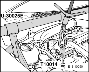
| t | counterhold -T10014-, see equivalent → Anchor |
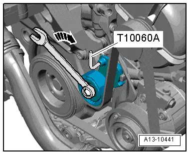
| t | Interlocking mandril -T10060 A-, see equivalent → Anchor |
| t | Bits -T10099-, see equivalent → Anchor |
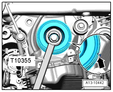
| t | Spanner -T10355-, see equivalent → Anchor |
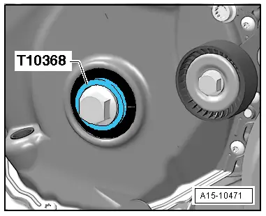
| t | Tappet -T10368-, see equivalent → Anchor |
| t | Bracket -U 30025E-, see equivalent → Anchor |
|
|
|
|
|
|
|
 Caution
|
|
|
|
 Note
Note
|
|
|
|
Note
|
|
|
|
|
|
|
|
Note
|
|
|
|
|
|
|
|
|
|
|
|
Note
|
|
 WARNING
Note
|
|
|
|
|
|
Note
|
|
Note
|
|
|
|