seat Workshop Repair Guides

SEAT Workshop Service and Repair Manuals

Valve for oil pressure controlN428: Removal and installation (engine codes CCZB - CDAA) > < Oil pump: removing and installing
Remove and install the upper element of the oil tray
Removing → Anchor.
Installing → Anchor.
   
Consult the equivalence table for tools and equipment according to applicability among Seat / VW / Audi / Skoda → Chapter.
Special tools and workshop equipment required
t  Testing equipment for brake pad wear -VW 136-, see equivalent → Anchor
t  Assembly tool -T10118-, see equivalency → Anchor
t  Torque wrench -V.A.G 1331-, see equivalent → Anchor.
t  Silicone sealant -D 174 003 A2-
  W17-10010
t  Used oil collection and extraction unit -V.A.G 1782-, see equivalent → Anchor
Removing
l  Gearbox removed
–  Remove oil pump → Chapter.
–  Remove the rear sealing flange on the gearbox side → Chapter.
  W00-10211
–  Release the fasteners -1 and 2- to remove the central soundproofing sump.
–  Remove the front right wheel housing liner, loosen the retainers -1, 2, 3- for this purpose.
  A10-10761
–  Remove bolts -arrows-.
–  Remove the air conduit tube, lifting the clips -1 and 2- for this purpose.
  A21-10162
–  Remove bolt -1-.
–  Unscrew the line bracket on the upper element of the oil sump next to the coolant circulation pump -V51-.
  A21-10161
–  Disconnect connector -1-.
  A17-10421
–  Remove bolts -arrows-.
  DANGER!
Injury risk! The chain tensioner spring for oil pump drive jumps from sump (top section) to timing chain cover (bottom) when detaching sump (top section). Do not reach between sump (top section) and timing chain cover (bottom) when removing sump (top section).
  N17-10200
–  Unscrew bolts -1 to 14- and remove the upper part of the sump.
  Caution
First remove the upper element of the oil sump on the gearbox side. Lift carefully so that the cover and the chain do not deform.
Fitting
l  Tightening torques → Chapter
t  Silicone sealant → Spare parts catalogue
  Note
t  Note expiry date of silicone sealant.
t  There is a 5-minute time limit for fitting the upper part of the sump once the silicone sealant has been applied.
  A17-10273
–  Fit the assembly tool -T10118- and pull the spring of the chain tensioner for the oil pump drive in the direction of the -arrow-.
–  Secure the spring. For this purpose, insert the testing equipment for brake pad wear -VW 136- into the borehole of the guide shoe as shown in the figure.
–  Remove sealant residue on cylinder block with a flat scraper.
  WARNING
Wear eye protection.
  N17-10163
–  Eliminate sealant paste remains from the upper oil sump element with, for example, a rotating plastic brush.
–  Clean sealing surfaces; they must be free of oil and grease.
  A13-0590
–  Cut off the tube nozzle on the front marking (diameter of the nozzle approximately. 3 mm).
  A17-0081
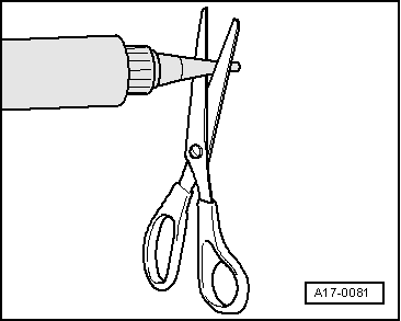
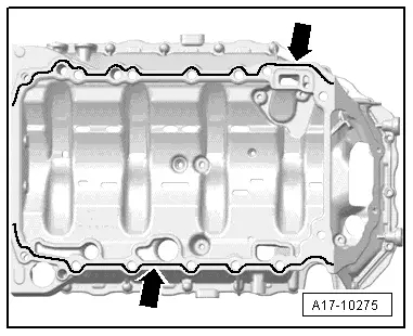
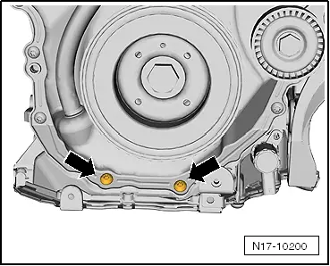
–  Apply a line of silicon sealant, as shown in the figure -arrows-, to the clean sealing surface of the upper oil sump.
t  Thickness of the sealant grub: 2 to 3 mm.
  Note
t  There is a 5-minute time limit for fitting the upper part of the sump once the silicone sealant has been applied.
t  The bead of sealant must not be thicker than specified, otherwise excess sealant can enter the sump and obstruct the strainer in the oil intake pipe.
l  The upper element of the oil sump and the crankshaft sump must connect flush on the gearbox side.
  A17-10275
–  Then position the upper element of the oil sump and then tighten the screws -1 to 14- in three stages as follows:
1 - Tighten the bolts by hand.
2 - When tightening bolts, apply 15 Nm torque
3 - Turn bolts 90° further.
  A17-10273
–  Fit bolts -arrows-. Tightening torque → Fig.
  N17-10200
–  Remove the testing equipment for brake pad wear -VW 136- from the guide shoe -arrow-. The spring returns to its initial position.
–  Mount the sealing flange (gearbox side) → Chapter.
–  Install oil pump → Chapter.
–  Renew baffle plate.
–  Install sump (bottom section) → Chapter.
–  Fill up with engine oil and check oil level → Booklet101.
Further assembly is basically the reverse of the dismantling sequence.
  N17-10201

Valve for oil pressure controlN428: Removal and installation (engine codes CCZB - CDAA) > < Oil pump: removing and installing