
Leon Mk1
|

| 1 - | Conrod bolt |
| q | With 1.8 litre engine: tighten to 30 Nm + a further 90° |
| q | With 2.0 litre engine: tighten to 45 Nm + a further 90° |
| q | Replace |
| q | Oil threads and contact surface. |
| q | Use old bolts when measuring radial clearance |
| q | When measuring radial clearance, tighten to 30 Nm but do not turn further |
| 2 - | Conrod bearing cap |
| q | Note fitting position: |
| q | Rods divided by fracturing (cracking) can only be fitted in one position and only with the corresponding conrod |
| q | Mark cylinder allocation -A- |
| q | Installation position: Marking -B- faces towards pulley end. |
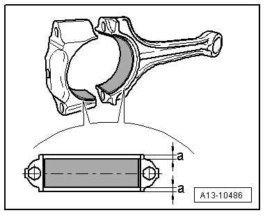
| 3 - | Bearing shells |
| q | Installation position → Fig. |
| q | Do not interchange used bearing shells (mark). |
| q | New axial play: 0,10...0,35; Wear limit: 0.40 mm |
| q | Check the radial play using a Plastigage thread; new: 0.02 to 0.06 mm; Wear limit: 0.09 mm do not rotate the crankshaft during the radial play measurement |
| 4 - | Pressure release valve |
| q | 27 Nm. |
| q | Opening pressure 1.6 to 1.9 bar. |
| 5 - | Oil spray jet |
| q | For piston cooling |
| 6 - | Circlip |
| 7 - | Piston pin |
| q | If difficult to remove, heat piston to approx. 60 °C |
| q | Remove and install with the installation tool -VW 222 A-, see equivalent → Anchor |
| 8 - | Piston |
| q | check → Fig. |
| q | Mark installation position and cylinder number. |
| q | Arrow on piston crown points to pulley end |
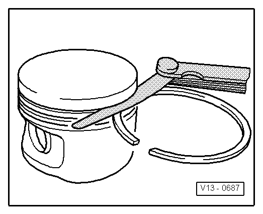
| q | Install using piston ring clamp |
| q | Piston and cylinder dimensions → Chapter |
| q | Checking cylinder bore → Fig. |
| 9 - | Compression rings |
| q | Displace the gaps at 120° from each other |
| q | Use piston ring pliers to remove and install |
| q | The inscription „TOP“ must face towards piston crown |
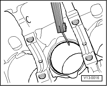
| q | Checking ring gap → Fig. |
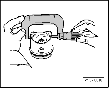
| q | Checking ring-to-groove clearance → Fig. |
| 10 - | Oil scraping ring |
| q | 3-part |
| q | Offset gap of top steel element of piston ring by 120° to next compression ring |
| q | Install gaps of the oil scraper ring parts offset to each other |
| q | Checking ring gap → Fig. |
| q | Axial play cannot be measured |
| 11 - | Conrod |
| q | Only a complete set may be replaced |
| q | Mark cylinder allocation -A- |
| q | Installation position: Marking -B- faces towards pulley end. |
|
|
| Piston ring Dimensions in mm | When new | Wear limit |
| compression ring | 0,20...0,40 | 0,8 |
| Oil scraping ring | 0,25...0,50 | 0,8 |
|
|
| Piston ring Dimensions in mm | When new | Wear limit |
| 1. compression ring | 0,04 … 0,08 | 0,15 |
| 2. compression ring | 0,02 … 0,06 | 0,15 |
| Oil scraper rings | cannot be measured | |
|
|
 Note
Note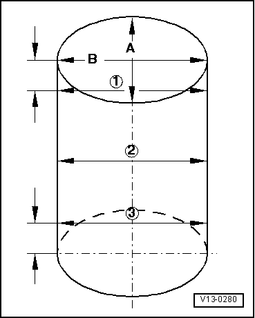
|
|