seat Workshop Repair Guides

SEAT Workshop Service and Repair Manuals

Injection system > < Charge air system
Engine control unitJ623 with antitheft protection: removal and installation (Altea, Altea XL, Leon)
Engine control unit -J623- with antitheft protection: removal and installation (Altea, Altea XL, Leon)
When replacing the engine control unit
To replace the engine control unit, connect the vehicle diagnostic tester and complete the guided function „Engine control unit: replace“.
t  Removing → Anchor.
t  Installing → Anchor.
Consult the equivalence table for tools and equipment according to applicability among Seat / VW / Audi / Skoda → Chapter.
Special tools and workshop equipment required
   
t  Plate work saw -VAG 1523B-, see equivalent → Anchor
t  Hot air blower, 220V/ 50 Hz -VAS 1978/14A--1- (of the wiring harness repair set -VAS 1978B-)
Removing .
–  Switch off ignition and remove ignition key.
–  Remove the front plate of the plenum chamber → Bodywork exterior fitting work; Rep. gr.50.
  Note
  W00-0005
t  The engine control unit -1- is bolted to a protective casing -2, 5-. To make it even more difficult to undo the breakaway bolts -3, 4- on the locking device-2-, a threadlocker has been used.
t  To disconnect connectors on the engine control unit (e.g. when connecting the testing box or to replace the engine control unit), the protective casing must be removed.
  A24-0593
–  Open the clip-in the direction of the arrow- and remove the engine control unit.
  A24-10451
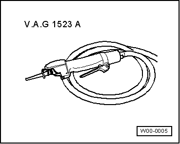
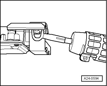
Using the body saw -VAG 1523B- make a groove on the heads of the shear screws for inserting a screwdriver.
  Note
t  
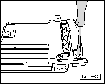
The groove must be wide enough in order to be able to screw out the screws using an appropriate screwdriver.
t  
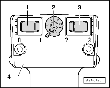
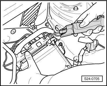
The thread on the shear screws can been treated with a threadlocker. For making sure that unscrewing is easier, you can warm the shear screws using the Hot air blower -VAS 1978/14A-. In doing so, take care that no bordering cables, plugs or components are damaged! .
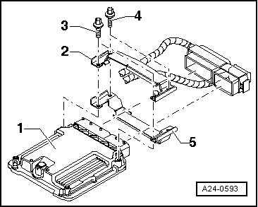
  WARNING
The threads of the two shear screws which are screwed into the engine control unit are not secured with locking fluid. Do not apply heat to the threads in the control unit housing; this is not necessary and would cause overheating of the control unit.
The threads of the shear screws which are not screwed into the engine control unit are not secured with locking fluid. To unscrew these bolts, the threads must therefore be heated with the hot-air blower.
To ensure that damage (burning) is not caused to the cables and connectors as well as insulation and control units, the following steps must be observed in all cases: Remember the instructions for using the hot-air gun.
  S24-0705
To prevent access to the engine control unit plug connectors, the engine control unit -1- is screwed on with an arresting element -2 and 5- and tear-off screws -3 and 4-.
Perform settings on hot air blower -4- as shown:
  A24-0593
–  Turn temperature setting potentiometer -2- to maximum heat output (600°C).
–  Set two-stage switch for volume of air -3- to position 3.
  WARNING
The threads of the two shear screws which are screwed into the engine control unit are not secured with locking fluid. Do not apply heat to the threads in the control unit housing; this is not necessary and would cause overheating of the control unit.
When breakaway bolts are heated, some parts of the protective casing become very hot. Risk of burn injuries! Also, make sure that, as far as possible, you only heat the breakaway bolt and not adjoining parts. If necessary, cover these parts.
  Note
  A24-0476
Then use hot air blower to heat shear screws -4-. This reduces the strength of the threadlocker on the thread of the breakaway bolts to make them easier to remove.
  A24-0593
–  Bring the nozzle of the hot-air gun up to the breakaway bolt on the lock.
–  Connect hot air gun and heat the head bolt approx. 20 to 25 seconds.
  A24-0594
–  Unscrew the shear screws using a screwdriver.
Separate the protective casing from the engine control unit.
–  Now release connector on engine control unit and pull off connector.
  E23-10022
Installing .
Installation is carried out in the reverse order of removing, when doing this note the following.
–  Clean threaded holes for shear bolts to remove any residue from locking fluid. This can be done using a thread tap.
–  First connect the rear connector and next, the front connector to the engine control unit and lock.
–  It is essential that the protective casing -2, 5- is replaced onto the engine control unit.
–  Use new breakaway bolts.
–  Tighten the shear screws evenly, until the screw heads break off.
  A24-0593
–  Insert the engine control unit in the bracket until you can hear the lock -arrow- engaging.
–  Fit the front panel on the plenum chamber → Bodywork - exterior installation work; Rep. gr.50.
When replacing the engine control unit
–  Adjust the new engine control unit.
–  Consult fault memory; if necessary, repair any faults and then erase fault memory → Vehicle diagnostic tester„guided fault finding“
–  The readiness code must be generated if the fault memory has been erased.
–  Perform road test.
–  Read control unit fault memory again.
–  Install wiper arms → Electrical system; Rep. gr.92
  A24-10451

Injection system > < Charge air system