seat Workshop Repair Guides

SEAT Workshop Service and Repair Manuals

Engine lubrication > < Replacing valve shaft seals.
Removing and installing timing chain and chain drive for oil pump
t  Removing → Anchor
t  Fitting → Anchor
t  Tightening torques → Anchor
   
Consult the equivalence table for tools and equipment according to applicability among Seat / VW / Audi / Skoda → Chapter.
Special tools and workshop equipment required
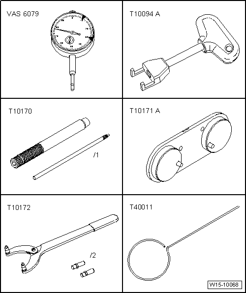
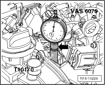
t  Gauge -VAS 6079-, see equivalent → Anchor
t  Extractor -T10094A-, see equivalent → Anchor
t  Adjustment tool -T10170-, please see Correspondence → Anchor
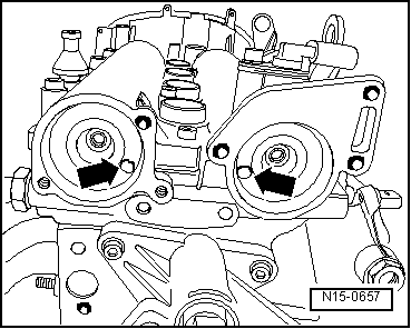
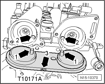
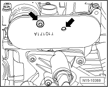
t  Adjustment tool -T10171A-, please see Correspondence → Anchor
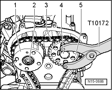
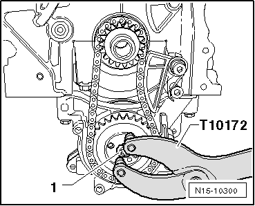
t  counterhold -T10172-, see equivalent → Anchor
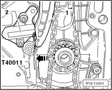
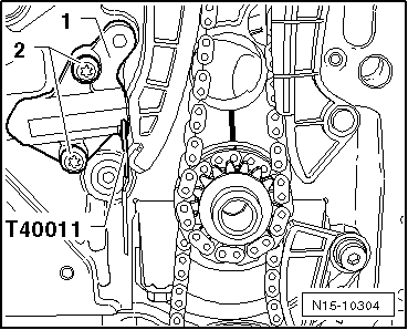
t  Hose clamp -T40011-, see equivalent → Anchor

   
t  Spanner -3122B-, see equivalent → Anchor
t  Hose clamp -3415-, see equivalent → Anchor
t  Hose clamp -3415/1-, see equivalent → Anchor
t  Torque wrench -VAG 1331-, see equivalent → Anchor.

   
Removing
–  Lift the engine cover by the positions -1- and push the cover forwards in the direction of the -arrow-.
–  Remove air cleaner housing → Chapter.
–  Drain coolant → Chapter
–  Unscrew the screw → Item and remove the air filter housing upwards.
  E10-10077
–  Remove the coolant hose from the hose clip -arrow-.
–  Unscrew the securing screws and remove the sealing cover of the camshaft -1-.
–  Remove the cylinder 1 spark plug. To do so, use the extractor -T10094A- and the wrench -3122B- → Chapter.
  N15-10225
–  Release connector -2- and pull off.
–  Remove oil pressure switch -F1--1-.
  N15-10696
–  Tighten the adjustment tool -T10170- as far as possible on the thread of the spark plug.
–  Insert the gauge -VAS 6079- with the extension -T10170/1- as far as it will go and tighten it with the clamping nut -arrow-.
–  Turn the crankshaft in the direction of engine rotation to TDC cylinder 1 . Observe the position of the small pointer of the gauge.
  N15-10226
The openings -arrows- of the camshafts should be in the positions shown. Where necessary, turn the crankshaft one turn (360°).
  Note
t  When the crankshaft rotates more than 0.01 mm beyond the TDC, the crankshaft must be rotated by approx. 45° against the direction of the engine again. Then turn crankshaft in direction of engine rotation to TDC No. 1 cylinder.
t  Permissible deviation from TDC cylinder 1: ± 0.01 mm
  N15-0657
–  Fit the adjustment tool -T10171A- as far as possible into the openings of the camshaft.
Locking pins -arrows 1- must engage in holes -arrows 2-. Inscription „TOP“-arrow 3- must be readable from above.
  N15-10370
–  For securing the camshaft fastener -T10171A-, screw an M6 screw -arrow- in the respective hole by hand (do not tighten).
  Note
Note that there are different securing points for the camshaft clamp -T10171 A-.
–  Remove valve timing housing → Chapter.
  N15-10369
–  Pull cover -1- off chain sprocket for oil pump.
  N15-10302
–  Push the tensioning rail by hand in the -direction of the arrow- and lock the piston of the chain tensioner using the retention tool -T40011-.
  N15-10301
–  Mark direction of rotation of timing chain -3- using coloured felt tip marker pen.
  Note
The camshaft adjuster securing bolt -2- has a left-hand thread.
–  Unscrew bolts -2- and -4- and remove camshaft adjuster -1- with timing chain -3-. To lock, use the retention tool -T10172-.
  N15-0686
–  Lock the oil pump sprocket using the retention tool -T10172- and undo the fastening bolt -1-.
  N15-10300
–  Use a screwdriver on bolt -2- to release tensioning spring -1- then remove tensioning spring -1-.
–  Unscrew securing bolt -3- and remove chain tensioner.
–  Mark direction of rotation of oil pump drive chain -2- using felt-tip marker.
  N15-10299
–  Undo the fastening bolts of the sprocket -1- and remove the sprockets -1- and -3- together with the oil pump control chain -2-.
Fitting
l  The crankshaft must be positioned at TDC No. 1 cylinder.
  N15-10298
–  Move the sprocket -1- in the -direction of the arrow - as far as possible along the crankshaft journal.
  Caution
Cast lug -2- on chain sprocket -1- must seat in groove -3- on crankshaft journal.
  N15-10309
–  Mark the positions of the sprocket and the crankshaft with respect to the cylinder block using a felt-tip pen.
  N15-10308
–  Place oil pump drive chain -3- onto drive chain sprocket -1- and position drive chain sprocket -2- onto oil pump drive shaft at same time.
  Note
t  Note running direction mark on oil pump drive chain.
t  Oil pump drive sprocket only fits on oil pump drive shaft in one position -arrow-.
  N15-10307
–  Lock the oil pump drive wheel using the retention tool -T10172-.
–  Tighten fastening screw -1- to 20 Nm + 1/4 turns (90°).
  N15-10300
–  Position chain tensioner on oil pump drive chain and tighten securing bolt -3- to 8 Nm.
–  Lever tensioning spring -1- onto bolt -2- using a screwdriver.
  Note
t  Note marks -arrows-.
t  The crankshaft must not rotate.
  N15-10299
–  Tighten chain sprocket -3- hand-tight with new securing bolt.
–  Place timing chain -1- on crankshaft chain sprocket -4-, exhaust camshaft chain sprocket -3-, and tighten camshaft adjuster -2- hand-tight using a new securing bolt.
  Note
t  Observe the mark showing the direction of rotation of the distribution chain -1-.
t  Ensure guide sleeve is installed between inlet camshaft and camshaft adjuster.
t  The camshaft adjuster securing bolt -2- has a left-hand thread.
  N15-10306
The distribution chain should rest on the guide rail -1- and on the crankshaft sprocket -arrow-.
  N15-10305
–  Fit the chain tensioner -1- and tighten the securing bolts -2- to a torque of 9 Nm.
–  Tension the distribution chain by removing the retention tool -T40011- from the tensioning device.
–  Check marks on crankshaft chain sprocket and cylinder block; they must align.
  N15-10304
–  Tighten the fastening bolt -2- to a torque of 40 Nm and bolt -4- to a torque of 50 Nm (use retention tool -T10172-).
  Note
t  Securing bolts -2- and -4- are only tightened 90° further once timing has been checked.
t  The camshaft adjuster securing bolt -2- has a left-hand thread.
  N15-0686
–  Undo bolt -arrow- and remove the retention tool -T10171A- from the camshaft casing.
–  Check distribution timing → Chapter
If valve timing is OK:
  N15-10369
–  Lock the camshaft sprockets using the retainer tool -T10172- and tighten the securing bolts -2- (left-threaded) and -4- using a spanner by 1 /4 turn. (90°).
  Note
t  The camshaft adjuster securing bolt -2- has a left-hand thread.
t  Camshaft sprockets must not move on camshaft whilst tightening.
  N15-0686
–  Install oil pump wheel cover -1-.
–  Install timing housing → Chapter.
–  Install crankshaft pulley → Chapter.
–  Install poly V-belt → Chapter.
–  Replace the seals of the camshaft covers and lubricate with oil before assembly.
Continue installation following reverse order for removing.
Tightening torques
  N15-10302
Components:Nm
Screw of the gear sprocket of the oil pump20 Nm + retighten 1/4 turn (90º)
Screw of the chain tensioner and drive chain of the oil pump15
Screw of the distribution chain tensioner9
Middle screw of the converter 40
Screw of the camshaft gear wheels50
 Oil pressure switch -F1-25


Engine lubrication > < Replacing valve shaft seals.