seat Workshop Repair Guides

SEAT Workshop Service and Repair Manuals

Turbocharger > < Charge air system
Removing and installing supercharger
t  Removing → Anchor
t  Installing → Anchor
   
Consult the equivalence table for tools and equipment according to applicability among Seat / VW / Audi / Skoda → Chapter.
t  Pliers for spring-loaded band-type clamps -VAS 6340-, see equivalent → Anchor
t  Torque wrench -VAG 1331-, see equivalent → Anchor.
t  Guide pins -T10341-, see equivalent → Anchor
t  Hose clamp -T10060A-, see equivalent → Anchor

   
t  Clip -3093-
Removing
  Note
To carry out this work it will be necessary to disconnect battery earth cable. Check whether a coded radio is fitted. Where necessary, check the anti-theft coding first.
–  Remove the earth wire of the battery when the ignition is turned off and lay to the side.
–  Observe rules for cleanliness → Chapter.
–  Remove the primary catalytic converter with exhaust pipe → Chapter.
  W00-0671
–  Lift the engine cover by the positions -1- and push the cover forwards in the direction of the -arrow-.
  E10-10077
–  Open the clamp -4- and remove the hose from the pressure tube -8-.
–  Unscrew bolts -2- and -7-.
–  Remove the mounting bar -1- and pressure pipe -8-.
–  Unscrew bolts -3- and -6-.
–  Remove the breather pipe -5-.
  S19-0334
–  Loosen the bracket -2- using the hose clip pliers -VAS 6499- and remove the hose -1-.
  E24-10060
–  Pull the plug connector from the intake air temperature sender 3 -G520--1- and from the regulating flap control unit -J808--6-.
–  Release hose clip -3-.
–  Remove bolts -arrows-.
–  Remove the breather pipe -4-.
–  Separate the intake support -2- from the pressure pipe.
  S24-0748
–  Unclip bracket -6-.
–  Remove the pressure pipe -5-.
  Note
Seal the opening using the engine plug set -VAS 6122-.
–  Release the cooling agent hose -7- from the bracket of charge air pipe -1-.
–  Unplug electrical connector -8- at charge pressure sender -G31-.
–  Undo screw -9- completely.
–  Undo the screw clamps -2- and -4- and separate the charge air hose -3- from the throttle valve.
–  Remove poly V-belt → Chapter.
  S21-0164
–  Undo the screw clamp -2- and disconnect the charger air hose -1- on the right side.
–  Loosen the screws -arrows- completely.
–  Remove the charger air pipe.
  E19-10047
–  Separate the fuel line -3- and the breather line -4- which goes to the activated carbon filter. To do so, press the unlock tabs.
  Note
Disregard item -2-.
–  Remove right-hand articulated shaft: → Running gear, shafts, steering; Rep. gr.40.
–  Unclip water hoses-1- and -2- using the hose clamps -3093-.
–  Open clips -arrows-.
  S10-0446
–  Disconnect the coolant hoses -1- and -2-.
  E10-10082
–  Opens clips for hose guides -2- and push hoses to one side.
  N21-10087
–  Unscrew and remove the bolts -arrows- of the pendulum support.
  N10-10308
–  Carefully press locking lugs on noise insulation housing -arrows- outwards.
–  Pull off front housing with noise insulation.
  N21-10196
–  Release the tension on poly V belt of the compressor by turning the tensioning element using the 16 mm open-ended spanner -T10241-.
–  Lock tensioner with retention tool -T10060A-.
  N19-10585
–  Unscrew securing bolts -arrows- for tensioning element and remove tensioning element.
  N21-10083
–  Lock the compressor shaft using an E/C 16 spanner -1-.
–  Unscrew the securing screws -2- from the pulley and remove the pulley and the Poly-V belt from the compressor -3-.
  N21-10086
–  Unscrew the bottom fixing screws -1- of the compressor and then screw the guide bolts -T10341- into both threaded holes to the end by hand.
–  Screw out the upper securing screws -2- of the compressor.
–  Press the engine to the front and remove the compressor.
  E21-10049
Removing noise insulation for charge air:
–  Remove the noise insulation for the charged air -2- to the rear together with the damping -arrow-.
Installing
  Note
t  Set the seals on the pressure pipe → Item
t  Before installing, lightly moisten O-rings with engine oil.
t  The pressure pipe can only be pushed in one position into the noise insulation for charge air (note locating element).
  N21-10094
–  Replace the sealing ring -1- and note the correct fit in the groove of the noise insulation for the charged air -2-.
–  Push the noise insulation for the charged air -2- onto the guide bolts -T10341- together with the damping -arrow-.
  N21-10094
–  Position the compressor and push onto the guide bolts -T10341-. Tighten the top securing bolts by hand -2-.
l  The setting sleeves of the noise insulation for the charged air must be correctly fitted to the cylinder head and on the compressor.
–  Unscrew guide pins -T10341-.
–  Screw in the bottom securing bolts by hand -1-.
  E21-10049
–  Tighten the securing bolts -1- and -2- equally and diagonally.
Tightening torque: 25 Nm.
–  Install supercharger belt pulley with poly V-belt positioned -3-.
  E21-10049
Tightening torque of the new fastening bolts -2-: 40 Nm + further 1/4 (90°).
–  Hold supercharger shaft with 16 mm spanner -1-.
–  Install tensioner.
  N21-10086
–  Tighten securing bolts -arrows- to 23 Nm.
  N21-10083
–  Hold tensioning element using 16 mm open-end spanner -T10241- and pull out locking pin -T10060 A-.
–  Position housing with noise insulation onto supercharger.
  Note
Ensure correct position of noise insulation in housing.
  N19-10585
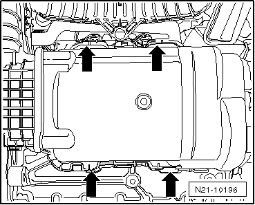
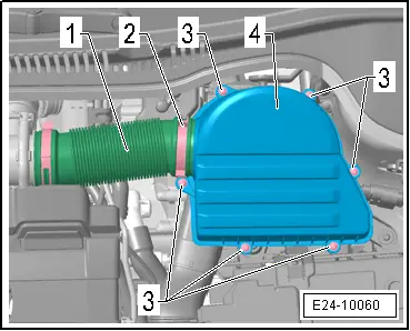
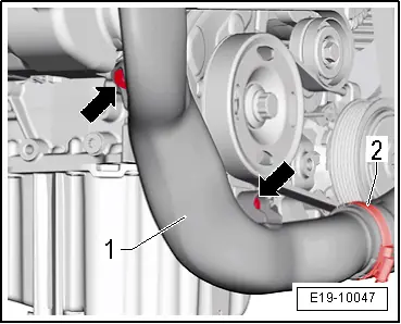
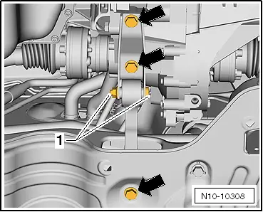
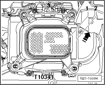
–  Press housing together with noise insulation against supercharger until locking lugs -arrows- click into place.
The remaining installation steps are carried out in reverse sequence - note the following points:
t  
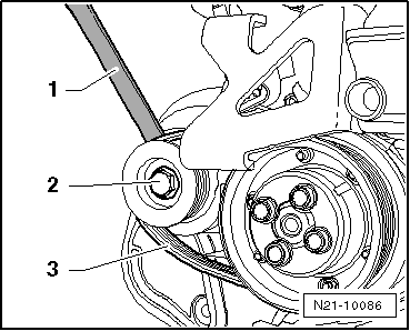
Renew securing bolt for supercharger pulley. Tightening torque: 40 Nm +1/4 turn further (90°).
t  Renew seals, gaskets and self-locking nuts.
t  
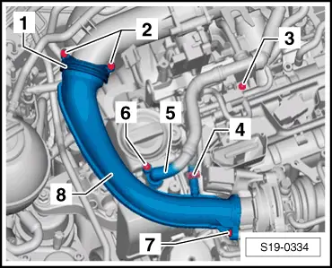
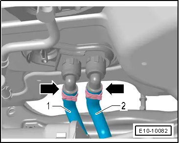
Hose connections and hoses for charge air system must be free from oil and grease before fitting.
t  Secure all hose connections with hose clips which conform to production standard.
–  Mount right-hand articulated shaft: → Running gear, shafts, steering; Rep. gr.40.
–  Mount the primary catalytic converter with exhaust pipe → Chapter.
Part I Poly V-belt drive - Assembly overview → Chapter
Catalytic converter and attaching parts - Assembly overview → Chapter
  N21-10196
–  Renew the O-rings of the pressure pipe -5-.
–  Note the correct alignment of the pressure pipe -5- on the noise insulation for the charged air -arrow-.
Tightening torques:
Assembly overview - charge air system → Chapter.
Installing hose connections with connector couplings → Chapter.
  Caution
The screw-type clips on the charge air pipes must be tightened to 5.5 Nm. If the torque is too low or too high, the charge air hose may slip off the charge air pipe during vehicle operation.
Install exhaust system and align it free of stress.
Continue installation following reverse order for removing.
–  Check coolant level and top up with coolant if necessary → Chapter.
  S21-0164

Turbocharger > < Charge air system