
Leon Mk1
| Assembly overview |
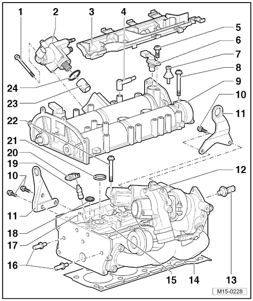
| 1 - | 20 Nm |
| 2 - | High-pressure pump |
| q | For fuel supply. |
| q | With fuel pressure regulating valve -N276- |
| q | Removing and installing → Chapter. |
| 3 - | Wiring guide |
| q | Bolt to camshaft housing with 8 Nm torque. |
| 4 - | Goes to the air filter |
| 5 - | 10 Nm |
| 6 - | Hall sender -G40- |
| q | With O-ring |
| q | Renew O-ring if damaged. |
| 7 - | Stud, 6 Nm |
| 8 - | 10 Nm +1/4 turn further (90º) |
| q | Replace |
| q | Tighten from centre outwards |
| 9 - | Camshaft housing |
 Note
Note| The strainer for oil circuit must be installed in cylinder head. |
| q | Removing and installing → Chapter. |
| q | Remove old sealant residues |
| q | Carefully clean sealing surfaces. They must be oil and grease free. |
| q | Before installing, coat with sealant -D 154 103 A1-. |
| q | When installing, fit vertically from above onto studs and dowel pins. |
| 10 - | 20 Nm |
| 11 - | Attachment rings |
| 12 - | Turbocharger |
| 13 - | Oil pressure switch -F1-, 25 Nm |
| q | check → Chapter |
| q | In case of leakage, cut out and replace sealing ring |
| 14 - | Cylinder head gasket |
| q | Replace |
| q | Metal gasket |
| q | If renewed, change coolant in entire system |
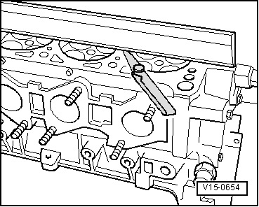
| 15 - | Cylinder head |
Note| The strainer for oil circuit must be installed in cylinder head. |
| q | Removing and installing → Chapter. |
| q | Checking for distortion → Fig. |
| q | Sealing surfaces to camshaft housing must be oil and grease free. |
| q | If renewed, change coolant in entire system |
| 16 - | Guide pin |
| q | Tightening torque: 20 Nm |
| 17 - | Dowel pin |
| 18 - | ATF strainer |
| q | Inserted into cylinder head. |
| q | Replace |
| 19 - | Supporting element |
| q | Do not interchange |
| q | With hydraulic valve clearance compensation. |
| q | Lubricate contact surface |
| 20 - | Roller rocker arms |
| q | Check roller bearing for ease of movement. |
| q | Lubricate contact surface |
| q | ?When installing, secure to support element using securing clip. |
| 21 - | Seal |
Note| Note the different sealing types when removing and installing the camshaft housing → Chapter. |
| q | Replace |
| q | 4 units |
| q | Inserted into cylinder head. |
| 22 - | Cylinder head bolt |
| q | Replace |
| q | Follow installation instructions and sequence when loosening and tightening → Chapter. |
| 23 - | Roller tappet |
| q | Lightly coat contact surface with engine oil. |
| 24 - | O ring |
| q | Replace |
| q | Moisten with oil before inserting. |
|
|