Leon Mk1
| Assembly overview |
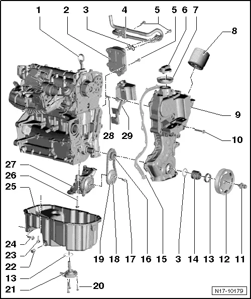
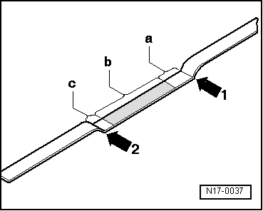
| 1 - | Oil dipstick |
| q | Oil level must not be above max. mark on dipstick! |
| q | Marks → Fig. |
| 2 - | Oil cooler |
| 3 - | O ring |
| q | Replace |
| 4 - | Coolant pipe |
| q | For oil cooler. |
| q | Tightening torque of the bracket on the crankshaft sump: 20 Nm |
| 5 - | 8 Nm |
| 6 - | Plug |
| q | Replace gasket if it shows signs of damage. |
| 7 - | Seal |
| q | Replace if damaged |
| 8 - | Oil filter, 20 Nm |
| q | Loosen with oil filter tool -3417-. |
| q | Observe installation instructions on oil filter. |
| q | With non-return valve. |
| 9 - | Distribution housing |
| q | Additionally install with silicone adhesive sealant -D 176 501 A1-. |
| q | Removing and fitting the distribution casing → Chapter |
| q | When installing, install two -M6x80- studs in cylinder block and camshaft housing as a guide. |
| q | To guide valve timing housing, secure sump in position with two bolts. |
| 10 - | 10 Nm |
| 11 - | Securing bolt |
| q | Removing and installing crankshaft pulley → Chapter. |
| q | Replace |
| q | Contact surface for securing bolt must be free of oil and grease. |
| q | Oil threads before inserting. |
| q | Secure pulley against turning with counterhold -3415-. |
| q | The turning further angle can be measured with a commercial protractor. |
| 12 - | Pulley |
| q | With diamond coated washer |
| q | Contact surfaces of pulley must be free of oil and grease. |
| q | Poly-V belt: removing and installing → Chapter |
| q | Secure pulley against turning with counterhold -3415-. |
| 13 - | Seal |
| q | Replace |
| 14 - | Bush |
| q | Contact surfaces of bearing bush must be free of oil and grease. |
| 15 - | Seal |
| q | Replace if damaged |
| 16 - | Pinions |
| q | Removing and installing → Chapter. |
| q | For oil pump drive. |
| 17 - | 20 Nm +1/4 turn further (90º) |
| q | Replace |
| 18 - | Pinions |
| q | Removing and installing → Chapter. |
| q | For oil pump |
| q | Lock with counterhold -T10172-. |
| 19 - | Drive chain |
| q | Removing and installing → Chapter. |
| q | For oil pump |
| q | Before removing, mark direction of rotation (installation position). |
| 20 - | 10 Nm |
| 21 - | Oil level/oil temperature sender -G266- |
| q | Replace if damaged |
| q | Checking: → Current flow diagrams, Electrical fault finding and Fitting locations |
| 22 - | Oil drain plug, 30 Nm |
| q | With safety washer |
| q | Replace |
| 23 - | 13 Nm |
| q | Loosen and tighten flywheel end bolts only with long-reach Allen key -T10058-. |
| 24 - | 45 Nm |
| 25 - | Oil pan |
| q | Removing and installing → Chapter. |
| q | Clean sealing surface before installing |
| q | Install with silicone sealant -D 176 600 A1-. |
| 26 - | 14 Nm +1/4 turn further (90º) |
| 27 - | Oil pump: |
 Caution
|
| q | with oil suction pipe |
| q | Oil suction pipe tightening torque: 9 Nm |
| 28 - | 5 Nm |
| 29 - | Baffle plate |