
Leon Mk1
|

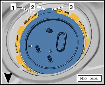
| 1 - | Fuel tank filler neck |
| q | With connection for earth cable to body. |
| q | Check for secure seating. |
| q | Screw onto body to 10 Nm. |
| 2 - | Retainer |
| 3 - | Clip |
| 4 - | Heat shield |
| 5 - | 25 Nm |
| q | Replace |
| 6 - | Line coupling |
| q | Separate to remove the fuel tank. |
| q | Release by pressing button on line coupling |
| 7 - | Ventilation / breather line |
| q | For the activated charcoal filter in right wheel housing |
| q | Separate to remove the fuel tank. |
| q | Release by pressing button on line couplings. |
| 8 - | Locking ring, 145 Nm |
| q | Remove and install using wrench -T10202-. |
| q | Check for secure seating. |
| 9 - | Flange on left |
| q | Installation position of flange → Fig. |
| q | Disconnect for removing suction-jet pump → Chapter |
| q | Assembly overview - fuel delivery unit with suction-jet pump → Chapter |
| 10 - | Fuel tank |
| q | When removing, support using engine and gearbox jack -V.A.G 1383 A-. |
| q | Removing and installing → Chapter. |
| 11 - | Securing strap on left |
| q | Note fitting position: |
| q | Check for secure seating. |
| 12 - | Securing strap on right |
| q | Note fitting position: |
| q | Check for secure seating. |
| 13 - | Metering pump -V54- |
| q | For auxiliary heater. |
| 14 - | Breather line |
| q | From activated charcoal filter solenoid valve 1 -N80- |
| q | To activated charcoal filter. |
| q | Separate to remove the fuel tank. |
| q | Release by pressing button on line couplings. |
| q | Check for secure seating. |
| 15 - | Fuel pump control unit -J538- |
| q | To remove, first lower fuel tank. |
| 16 - | Fuel filter: |
| q | With integrated fuel pressure regulator |
| q | Fitting position: The arrow indicates the direction of flow |
| q | Removing and installing → Chapter. |
| 17 - | Fuel delivery unit |
| q | With fuel level indicator sender -G- |
| q | Installation position of flange → Fig. |
| q | Assembly overview - fuel delivery unit with suction-jet pump → Chapter |
| q | Removing and installing → Chapter. |
| 18 - | Locking ring, 145 Nm |
| q | Remove and install using wrench -T10202-. |
| q | Check for secure seating. |
|
|