
Leon Mk1
| Distribution timing: adjustment |

| Special tools and workshop equipment required |
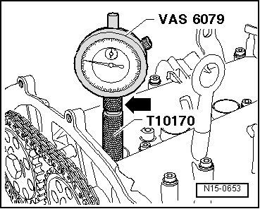
| t | Dial gauge -VAS 6079- |
| t | Extractor -T10094 A- |
| t | Dial gauge adapter -T10170- or dial gauge adapter -T10170 A- |
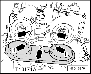
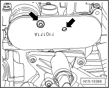
| t | Camshaft clamp -T10171 A- |
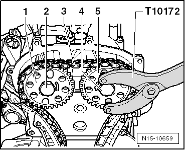
| t | Counterhold tool -T10172- |
| t | Locking pin -T40011- |

| t | Torque wrench -V.A.G 1601- |
| t | Counterhold tool -3415- |
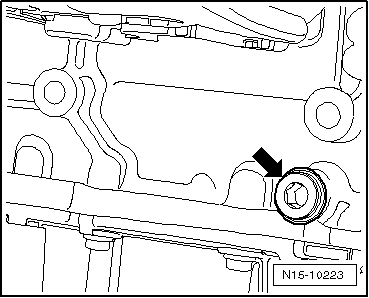
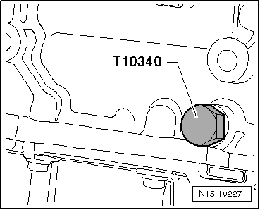
| t | Securing bolt -T10340- |
| t | Torque wrench -V.A.G 1331- |
|
|
|
|
|
|
|
|
|
|
|
|
|
|
 Note
Note
|
|
Note
|
|
Note
|
|
|
|
|
|
Note
|
|
|
|
|
|
|
|
Note
|
|
Note
|
|
|
|
|
|