seat Workshop Repair Guides

SEAT Workshop Service and Repair Manuals

Attaching engine to repair stand > < Engine: dismounting
Operation process
Operation process
–  With the ignition switched off, disconnect the battery earth lead → Electrical system; Rep. gr.27.
   
–  Unscrew the bolt -3- and remove the air filter housing together with the connecting hoses.
–  Remove the battery and its bracket
–  Remove the front plate of the plenum chamber → Bodywork, exterior fitting work; Rep. gr.55.
–  Disconnect the engine wiring harness connector from the control unit.
  A10-1570
–  Release the engine cable harness guide -arrow-, and pull out upwards.
  A10-1574
–  Open the catches of the cable guides on the longitudinal member -arrows-.
–  Separate the plug connectors between the wiring harness of the engine and the bodywork. Place the engine wiring harness on the engine.
  WARNING
Fuel supply line is pressurised. Wear safety goggles and appropriate clothing to avoid injury and contact with skin. Before loosening hose connections, wrap a cloth around the connection. Then eliminate the pressure by carefully separating the pipe.
  N10-0461
–  Separate the venting line -1- and fuel supply line -2- by pressing on the release tabs.
  A20-1065
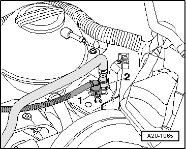
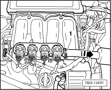
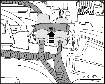
–  Loosen the bracket -1- and remove the hose from the gas distribution rail -in the direction of the arrow-.
–  Remove sound-proofing → Body, exterior assembly work; Rep. gr.50.
–  Place lock carrier into original position: → Bodywork, exterior fitting work; Rep. gr.50.
–  Drain coolant → Chapter.
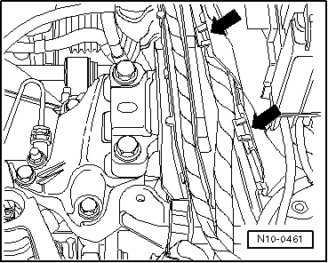
–  Disconnect / separate all other electrical connections from engine and gearbox as necessary and lay to one side.
–  Disconnect all other coolant, vacuum and intake hoses from the engine.
Vehicles with air conditioner:
  Note
In order to avoid damage to the condenser or the lines of the refrigerant, take care that pulling, bending or excessive twisting of the line is avoided.
Remove the engine without opening the refrigerant circuit:
–  Remove poly V-belt → Chapter.
–  Remove the air conditioner compressor from the subframe → Heating, ventilation, air conditioning; Rep. gr.87.
–  Attach the compressor to the lock carrier plate so that the refrigerant lines are not under any strain.
–  Remove the gear selection mechanism from the gearbox → 5-speed manual gearbox 0AF; Rep. gr.34
  N24-10591
–  Remove slave cylinder -arrows-, lay to one side and do not open pipe system.
  Note
Do not press on the clutch pedal after removing the reception cylinder.
–  Remove the primary exhaust pipe with catalytic converter → Chapter.
–  Remove pendulum support.
–  Unbolt the articulated shaft on the right and left sides from the gearbox → Running gear, shafts, steering; Rep. gr.40
  A30-0106
–  Unscrew the grub screw -arrow- at the front of the engine block.
–  Insert the engine bracket -T10012- into the engine and gearbox jack -V.A.G 1383 A-.
  A10-1639
–  Put the engine bracket -T10012- on as shown and screw on to the cylinder block with approx. 20 Nm using M10 × 25 screws.
–  Lift the engine and gearbox slightly with the engine and gearbox crane -V.A.G 1383 A-.
  N10-0056
–  Unbolt assembly mounting from above, engine side, from the engine bracket -arrows-.
  N10-0437
–  Unbolt assembly mounting from above, gearbox side, from the gearbox bracket -arrows-.
  Note
t  To remove securing bolts use a ladder -VAS 5085-.
t  Engine and gearbox must be guided carefully when lowering to prevent damage to the bodywork.
–  Carefully lower the engine and gearbox.
  N34-1846

Attaching engine to repair stand > < Engine: dismounting