seat Workshop Repair Guides

SEAT Workshop Service and Repair Manuals

Hall sender G40 : verification > < Exhaust system
Hall senderG40: verification
   
Hall sender -G40-: verification
Special tools and workshop equipment required
t  Hand multimeter -V.A.G 1526A- oder multimeter -V.A.G 1715-
t  Auxiliary measurement tool set -V.A.G 1594A- or -V.A.G 1594C-
t  Double connection engine testing unit -V.A.G 1598/31- (AZL engines) or -V.A.G 1598/22- (BBX engines)
t  Current flow diagrams

Function
Fitting location → Item.
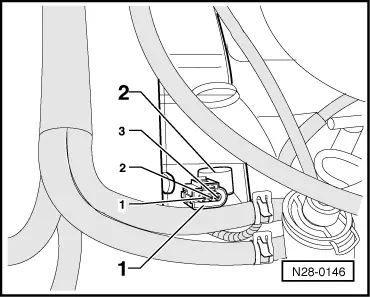
The Hall sender -G40- informs of the ignition position of cylinder 1.
If the sender ceases to function, the knock control is deactivated and the ignition angle is delayed, given that it is not possible to carry out an assignment of the cylinders.
Without the signal from the Hall sender -G40-, the engine will continue to function and start
If the fault is identified, the engine control unit will activate an ignition spark per cylinder for each turn of the crankshaft.
Test conditions
l  The fuses must be OK.
l  Battery voltage at least 11.5 V
l  Hall sender screwed on tight
Voltage supply: verification
   
–  Remove the connector -1- from the Hall sender -G40-.
–  Measure the voltage with the multimeter and the auxiliary cables of -V.A.G 1594 A- or -V.A.G 1594 C- as follows:
  N28-0146
Connector -1-, contactConnector -1-, contact
13

–  Turn the ignition on. Specification: approx. 5 V.
If the ideal value is not measured:
–  Verify the connections between the Hall sender -G40- and the engine control unit → Chapter.
   

Hall sender G40 : verification > < Exhaust system