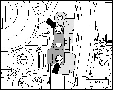
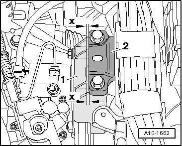
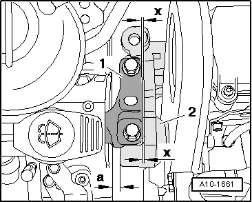
| The following dimensions must be reached: |
| l
| Between the engine support and the right longitudinal member there must be a distance of -a- = 16 mm. |
| l
| The moulded edge at the engine support foot -2- must be parallel to the support arm -1- (dimension-x- = dimension-x-). |

Note | The dimension -a- = 16 mm. can be checked, for example, with an appropriate cylindrical object. |
| If the gap is too narrow or too wide, proceed as follows → Anchor . |
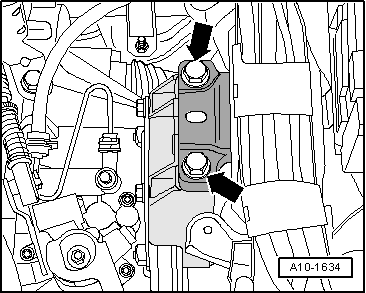
| Assembly mounting: adjusting |
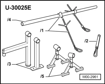
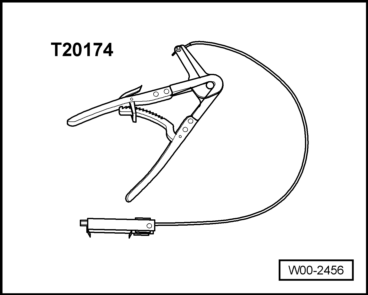
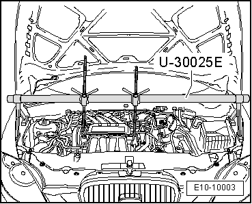
| Special tools and workshop equipment required |
|
|
|